Retractable car cover

a car cover and retraction technology, applied in the field of car covers, can solve the problems of the cover becoming jammed within the canister and leaving the trunk area unprotected, and achieve the effect of facilitating the rotation of the axl

Inactive Publication Date: 2005-11-15
PORTER MATTHEW B
View PDF17 Cites 35 Cited by
  • Summary
  • Abstract
  • Description
  • Claims
  • Application Information

AI Technical Summary

Benefits of technology

[0008]The cover includes several layers to yield a cover configured to protect the vehicle from the elements, inhibit scratching or other signs of wear on the vehicle during usage, and permit selective expansion of the cover in order to more fully cover the vehicle. More particularly, the preferred cover includes an outer, generally opaque, water resilient layer, a middle, elastic layer and an inner layer of protective padding. The elastic layer biases the cover toward a rest width substantially the same as the length of the aperture to facilitate extension and retraction of the cover to and from the housing, while permitting selective expansion of the cover. A pair of straps are attached to the side edges of the cover and may be selectively coupled to the lower portion of the sides of the vehicle in order to maintain the cover in the expanded condition.
[0010]A cover extension and retraction system is located in the housing. The system includes a ratchet wheel mounted on the axle and a pawl engaging the wheel permitting rotation of the wheel, and thus the axle in a first, counter-clockwise direction for extension of the cover. A release button is used to selectively disengage the pawl from the ratchet wheel to permit rotation of the wheel in a second, clockwise direction to permit retraction of the cover into the housing. A crank handle is coupled with the axle for facilitating rotation of the axle.

Problems solved by technology

This may result in unwanted bunching of the cover that will in turn result in the cover becoming jammed within the canister.
In addition, the cover only covers the cabin and forward hood areas of the car, leaving the trunk area unprotected.

Method used


Image

  • Retractable car cover
  • Retractable car cover
  • Retractable car cover

Examples


Embodiment Construction

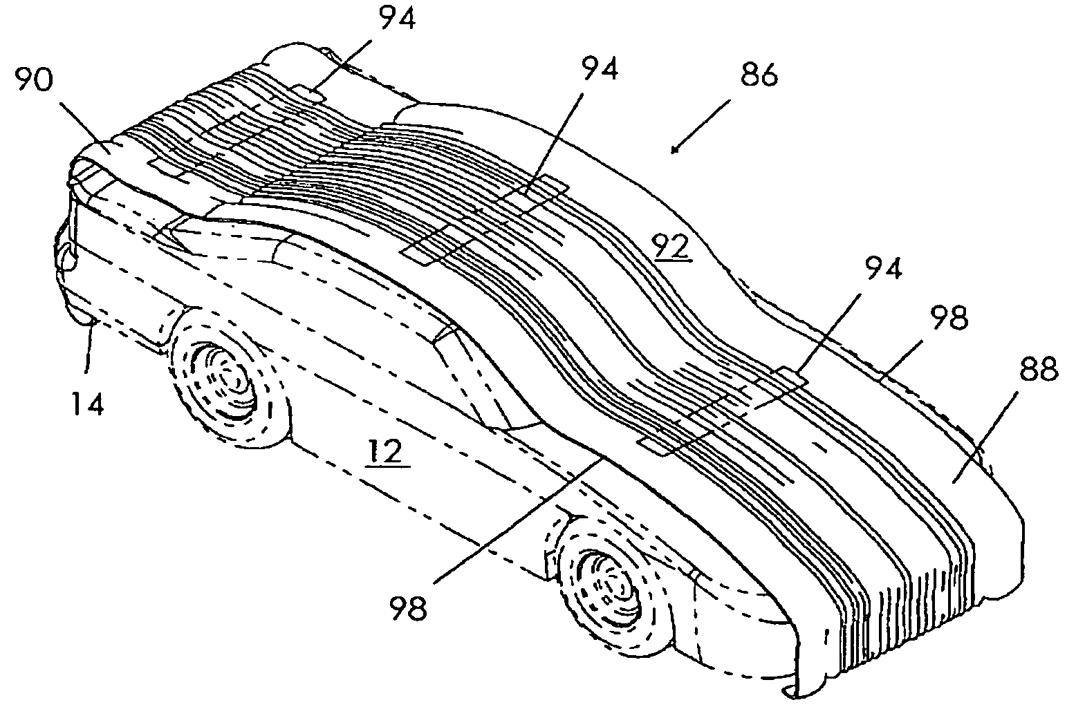
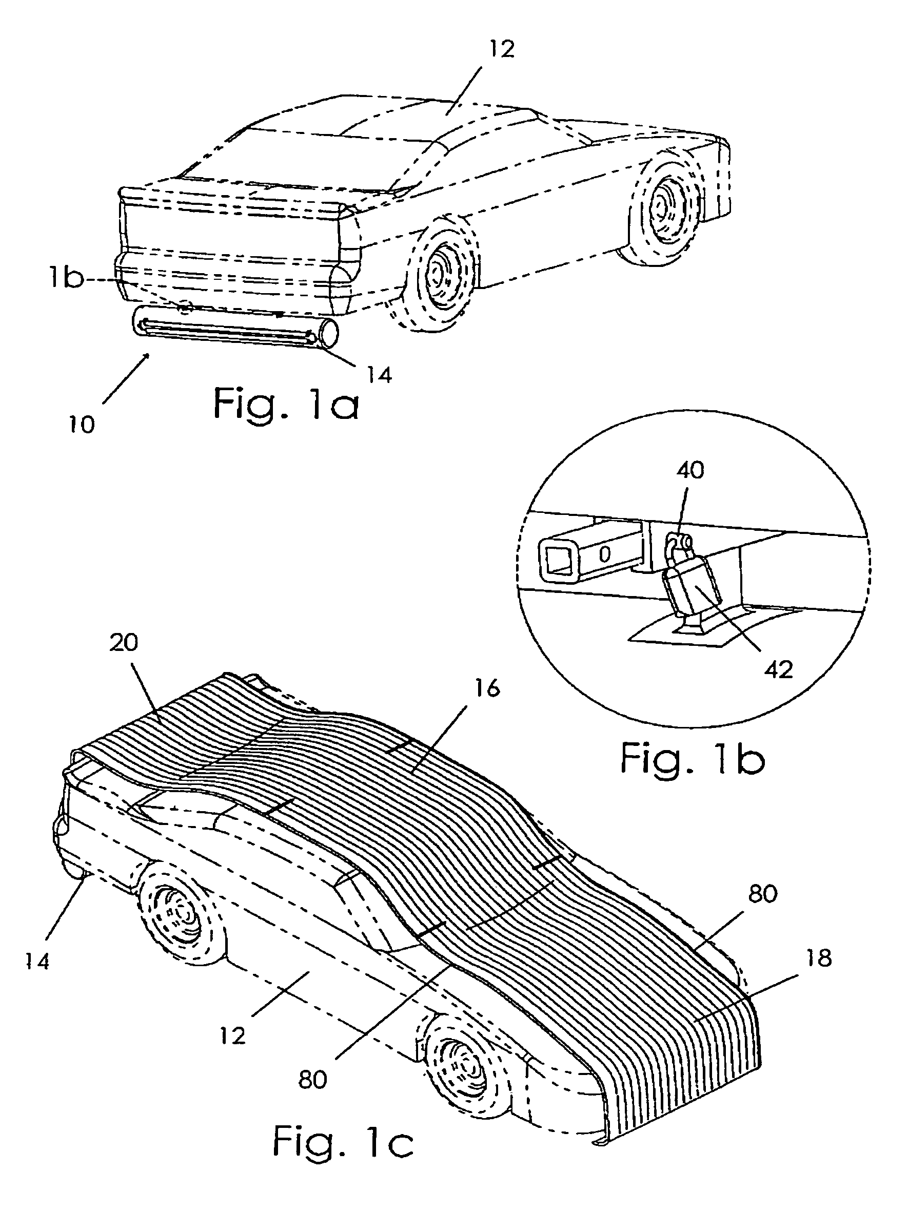
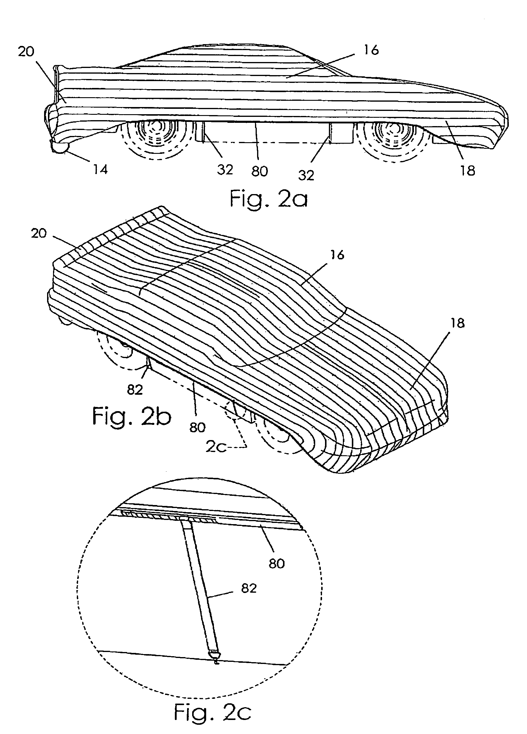
[0027]Referring now to the drawings, FIG. 1a depicts a retractable vehicle cover apparatus 10 constructed in accordance with a preferred embodiment of the present invention coupled to the frame of a car 12. The cover apparatus 10 broadly comprises an elongated, generally cylindrical housing 14 having side wall structure defining an interior cavity, and a cover 16 received in the cavity of the housing 14 for selective retraction and extension to and from the housing 14. The cover 16 includes a distal first end 18 and a proximal second end 20. The cover 16 is expandable to more fully cover the car 12, as shown in FIGS. 2a, 2b.

[0028]FIG. 4 depicts additional detail concerning some of the elements of the apparatus 10. An axle 22 is disposed within the cavity of the housing 14 for rotational movement about a central axis. The proximal end 20 of the cover 16 is coupled with the axle 22. The housing 14 includes side wall structure having an elongated aperture 24 presenting a length define...


PUM


Abstract

A retractable vehicle cover apparatus for covering a vehicle comprises an elongated, hollow housing, and axle disposed therein for rotation about a central axis, and an elongated cover having a proximal end coupled with the axle and also having a distal end. The housing includes wall structure having an elongated aperture defined through the wall structure. The cover is fed through the aperture for selective movement between a retracted position where the cover is wrapped around the axle, and an extended position where a substantial portion of the cover extends from the housing. The cover includes an outer layer of aligned cover strips, a middle, elastic layer and an inner layer of aligned padding strips. The elastic layer biases the cover toward a rest width substantially the same length as the aperture to facilitate extension and retraction of the cover, and permits selective expansion of the cover in order to more fully cover the vehicle.

Description

BACKGROUND OF THE INVENTION[0001]1. Field of the Invention[0002]The present invention relates generally to a car cover stored in a canister that is deployed to cover a car, protecting the car from natural elements. More particularly, the present invention includes a novel cover that assists in facilitating deployment and storage of the cover.[0003]2. Discussion of the Prior Art[0004]Retractable car covers are known in the prior art. For example, U.S. Pat. No. 4,856,842 to Ross et al., discloses a retractable car cover that is stored in a canister for selective deployment. The cover disclosed in the Ross reference is constructed from fabric commonly used in the art of car covers and is necessarily significantly wider than the canister. As a result, as the cover is retracted into the canister, the canister must mechanically gather the sides of the cover. This may result in unwanted bunching of the cover that will in turn result in the cover becoming jammed within the canister.[0005]Ot...

Claims


Application Information

Patent Timeline
Patent Type & Authority Patents(United States)
IPC IPC(8): B60J11/00
CPCB60J11/02
Inventor PORTER, MATTHEW B.
Owner PORTER MATTHEW B
Why Eureka
Try Eureka