Adhesive coating device

a coating device and adhesive technology, applied in the field of adhesive coating devices, can solve the problems of difficult to accurately control the final temperature of the coating roller from the heater, low heat transfer efficiency, and long time until a standby state, so as to achieve quick heating and shorten the starting time period

Inactive Publication Date: 2005-11-15
DUPLO SEIKO CORP
View PDF8 Cites 18 Cited by
  • Summary
  • Abstract
  • Description
  • Claims
  • Application Information

AI Technical Summary

Benefits of technology

[0014]In the above-mentioned configuration, the electromagnetic induction heating coil is not disposed in the peripheral direction of the roller but disposed on the side of the rotation shaft, that is, disposed so as to face the bottom face of the roller. In addition, the roller is configured so as to be hollow, and the face thereof on the side wherein the electromagnetic induction heating coil is disposed is made of a nonmagnetic substance, whereby the cylindrical roller with a bottom is disposed so as to be open in the direction toward the coil as viewed from the electromagnetic induction heating coil and an eddy current flows along the whole wall thereof. In addition, the side face on the side of the coil is sealed by a wall made of a nonmagnetic substance, whereby the adhesive can be prevented from entering the inside of the roller.
[0015]With the above-mentioned configuration, since the eddy current can flow around the whole peripheral wall of the roller, the roller can be heated quickly. Hence, a starting time period can be shortened.

Problems solved by technology

However, in such indirect heating means as that uses the above-mentioned heater, the efficiency of heat transfer is low; three steps of heat transfer, from the heater to the adhesive reservoir, from the adhesive reservoir to the adhesive and from the adhesive to the coating roller, are required to sufficiently heat the coating roller, which serves as a member for directly applying the adhesive to the back of the bundle of sheets, to a predetermined temperature.
Hence, it takes a long time until a standby state is attained, and it is difficult to accurately control the final temperature of the coating roller from the heater serving as a heat source.
In addition, since the roller serving as a secondary heating member is required to be capable of carrying out heat transfer and to have a volume capable of sufficiently storing heat, it is necessary to increase the volume of the roller; as a result, the whole device becomes larger in size.
Therefore, the atmospheric exposure area of the adhesive in the adhesive reservoir is required to be increased, causing problems of bad-smelling and the like.
However, in this type of device, the configuration of the coating roller itself becomes massive, resulting in making the whole device larger in size; in addition, since the coating roller is structured to rotate around its shaft, there is a problem of wire processing.
Furthermore, if adhesive attaches to the halogen lamp, this may cause breakage; therefore, it is necessary to use a structure wherein the halogen heater is replaceable and to provide a seal for preventing the adhesive from entering the open area provided in the coating roller.

Method used


Image

  • Adhesive coating device
  • Adhesive coating device
  • Adhesive coating device

Examples


first embodiment

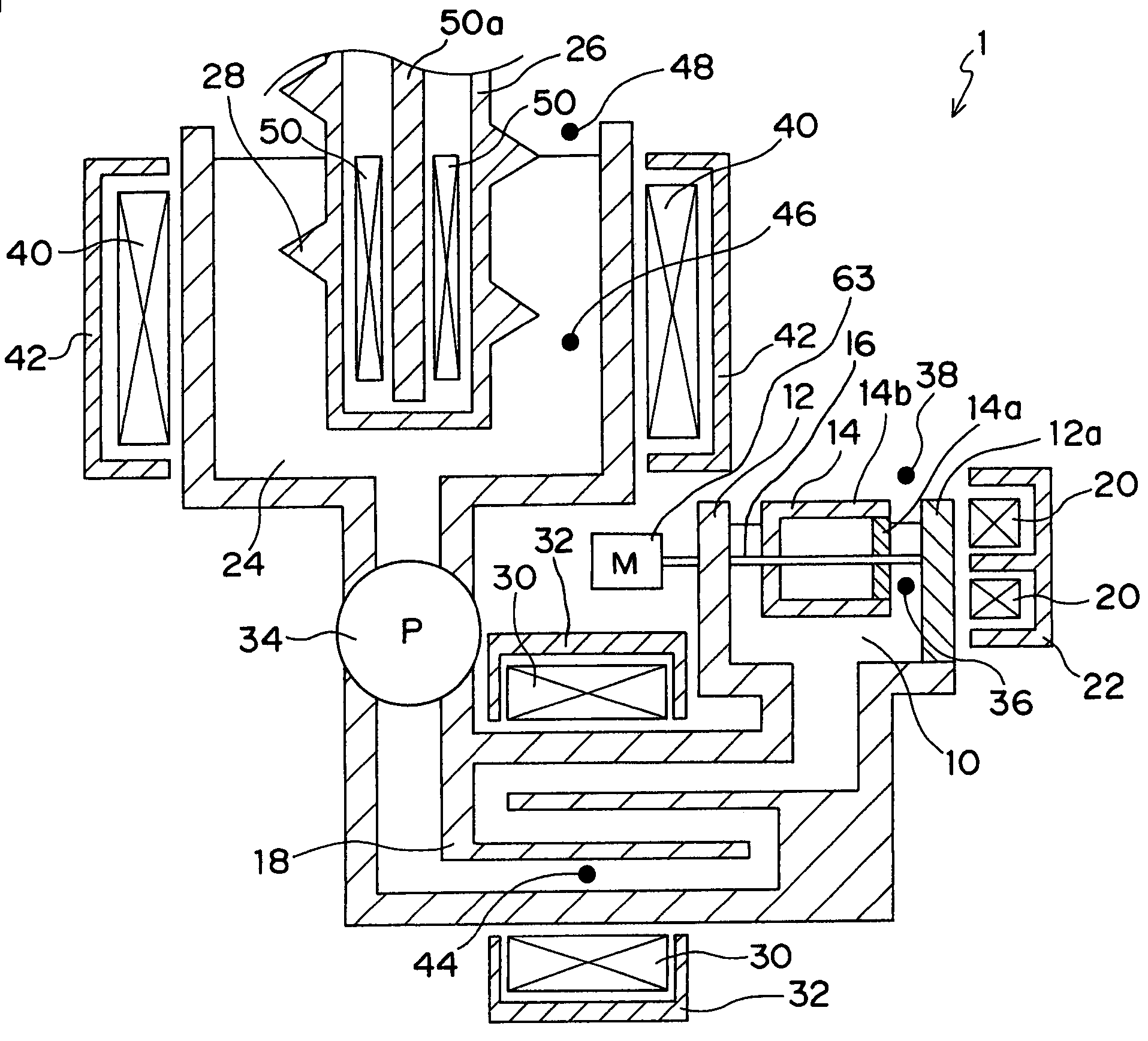
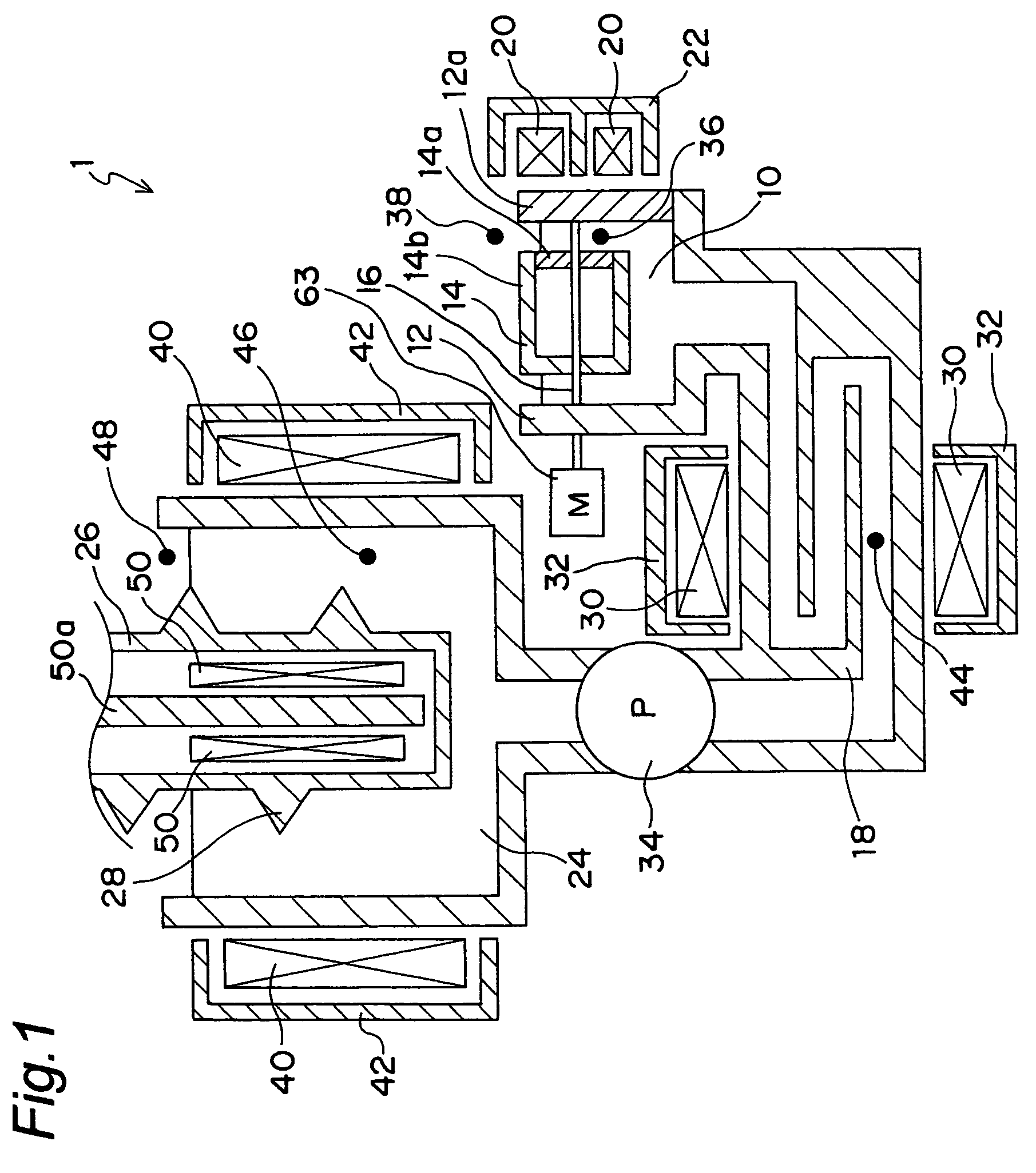
[0056]FIG. 1 is a view showing the main configuration of a sheet-binding device in accordance with the present invention. This sheet-binding device 1 comprises an adhesive reservoir 12 for storing hot-melt adhesive 10, a reservoir tank 24 for storing the adhesive to be replenished, and an adhesive supply section 18 for connecting the reservoir tank to the adhesive reservoir. In the adhesive reservoir 12, a roller 14 is provided. The roller 14 is journaled by a shaft 16 so that at least part of the peripheral face thereof is immersed in the adhesive stored inside the adhesive reservoir and that is rotatable around the shaft by a motor 63 connected to the shaft.

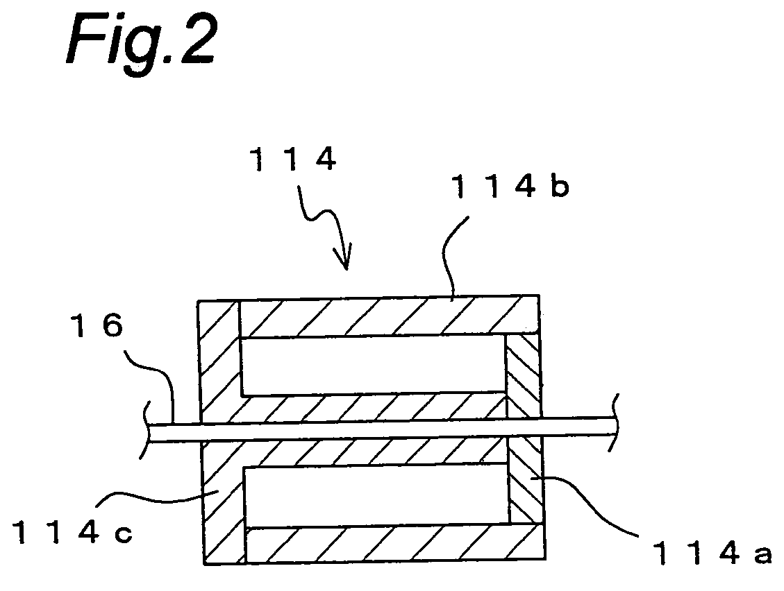
[0057]On the extension of the shaft 16 of the roller 14, a first heating coil 20 is provided. The roller 14 comprises a cup-shaped member 14b made of iron and a plate-shaped section 14a made of glass epoxy resin and constituting the side wall on the side facing the first heating coil so as to be configured in a hollow shape as ...

second embodiment

[0093]FIG. 14 is a view showing the main configuration of a sheet-binding device in accordance with the present invention. This sheet-binding device comprises an adhesive reservoir 12 for storing hot-melt adhesive 10, a reservoir tank 24 for storing the adhesive to be, replenished and an adhesive supply section 18 for connecting the reservoir tank to the adhesive reservoir. In the adhesive reservoir 12, a roller 14 that is journaled by a shaft 16 so that at least part thereof is immersed in the adhesive stored inside the adhesive reservoir and that is rotatable around the shaft by a motor 63 connected to the shaft is provided.

[0094]On the extension of the shaft 16 of the roller 14, a heating coil 20 is provided. The first heating coil 20 is configured so as to be able to receive a high-frequency current from a current supply device not shown. When the high-frequency current flows through the first heating coil 20, a magnetic flux is generated around it. The magnetic flux generated b...


PUM

PropertyMeasurementUnit
frequencyaaaaaaaaaa
diameteraaaaaaaaaa
volume resistivityaaaaaaaaaa

Abstract

The present invention relates to an adhesive coating device for sheet-binding provided with a roller 14, part of which is immersed in adhesive 10 stored in an adhesive reservoir 12, for applying hot-melted adhesive 10 in the above-mentioned adhesive reservoir 12 along the arranged one-side edge of a bundle of sheets 54 while rotating. The device includes an electromagnetic induction heating coil 20 disposed in the vicinity of the above-mentioned roller 14, and a current supply device 5 for supplying a high-frequency current to the above-mentioned electromagnetic induction heating coil 20. The above-mentioned roller 14 is formed of a heating member for generating heat using the Joule heat owing to an eddy current caused by a high-frequency magnetic flux generated by the above-mentioned electromagnetic induction heating coil 20, and the above-mentioned roller 14 is heated by supplying a current from the above-mentioned current supply device 51 to the above-mentioned electromagnetic induction heating coil 20 so that the adhesive 10 stored in the above-mentioned adhesive reservoir 12 is melted.

Description

TECHNICAL FIELD[0001]The present invention relates to an adhesive coating device used in a sheet-binding device and more particularly to a device for melting hot-meltable solid adhesive and applying the adhesive to the one-side edge of a bundle of sheets serving as the back of a book in a sheet-binding process.BACKGROUND ART[0002]Conventionally, a sheet-binding device or the like for applying adhesive to the back of a bundle of printed sheets and binding the sheets has an adhesive coating device provided with an adhesive reservoir for storing hot-melt adhesive and a coating roller disposed so that part thereof is immersed in the adhesive stored in the adhesive reservoir and so that the roller is journaled to be rotatable in the adhesive reservoir. The above-mentioned device, having been used in the mainstream, is provided with a heater in the adhesive reservoir so that the heater heats the adhesive to melt the adhesive.[0003]However, in such indirect heating means as that uses the a...

Claims


Application Information

Patent Timeline
Patent Type & Authority Patents(United States)
IPC IPC(8): B05C1/00B05C1/08B42C9/00B05C1/02B05C9/02B05C9/14B05C11/10B05C11/11H05B6/02H05B6/14
CPCB05C1/003B05C1/08H05B6/108H05B6/145B42C9/0012B05C1/006Y10T156/1798Y10S156/908B05C1/02
Inventor TANIGUCHI, CHIHARUSUGIYAMA, YOSHIHIDE
Owner DUPLO SEIKO CORP
Why Eureka
Try Eureka