Eureka AIR delivers breakthrough ideas for toughest innovation challenges, trusted by R&D personnel around the world.

Pole-top insulator

a technology of insulator and pole, which is applied in the direction of machine supports, other domestic objects, mechanical apparatus, etc., can solve the problems of increasing the erection or assembly time of each individual pole structure with associated insulators, and increasing the cost of erection and assembly

Inactive Publication Date: 2005-11-15
HITACHI ENERGY SWITZERLAND AG
View PDF15 Cites 2 Cited by
  • Summary
  • Abstract
  • Description
  • Claims
  • Application Information

AI Technical Summary

Benefits of technology

[0006]An additional object of the invention is to produce a pole-top insulator that considerably reduces the transverse span of the power line, i.e. its width, and which can be mounted on a pole leg or similar supporting structure as one prefabricated, compact, continuous unit.
[0007]Another object of the invention is to produce a power line carrier with a more compact design to form so-called compact lines, whereby the electromagnetic field surrounding the power line can be reduced and the aesthetic impression of the power line can be enhanced. It is further desirable to reduce the size of the carrier unit.

Problems solved by technology

One disadvantage with this known type of pole structure for power lines is that they require relatively long transverse bars to maintain the distance of the phase leads from each other and from the pole leg.
As this support arrangement is built transversely, this makes power lines not only very large but also aesthetically distasteful.
Furthermore, the said generally occurring support arrangement must be assembled or erected on site and in principle part by part, which is why the erection or assembly time for each individual pole structure with associated insulators becomes relatively long.
Not least, this leads to the construction and completion of a finished power line being relatively expensive.
This known, self-supporting, insulating arrangement has thus far been used exclusively for low-voltage lines due to the problem of achieving the necessary strength to withstand the forces that arise in high-voltage power lines.
In particular, it has proved to be difficult to overcome the strength problems that arise between the attachment points of the composite material or their transitional parts.
Furthermore, it has been difficult to achieve sufficiently long and reliable leakage paths in the self-supporting insulating parts.

Method used


Image

  • Pole-top insulator
  • Pole-top insulator
  • Pole-top insulator

Examples


Embodiment Construction

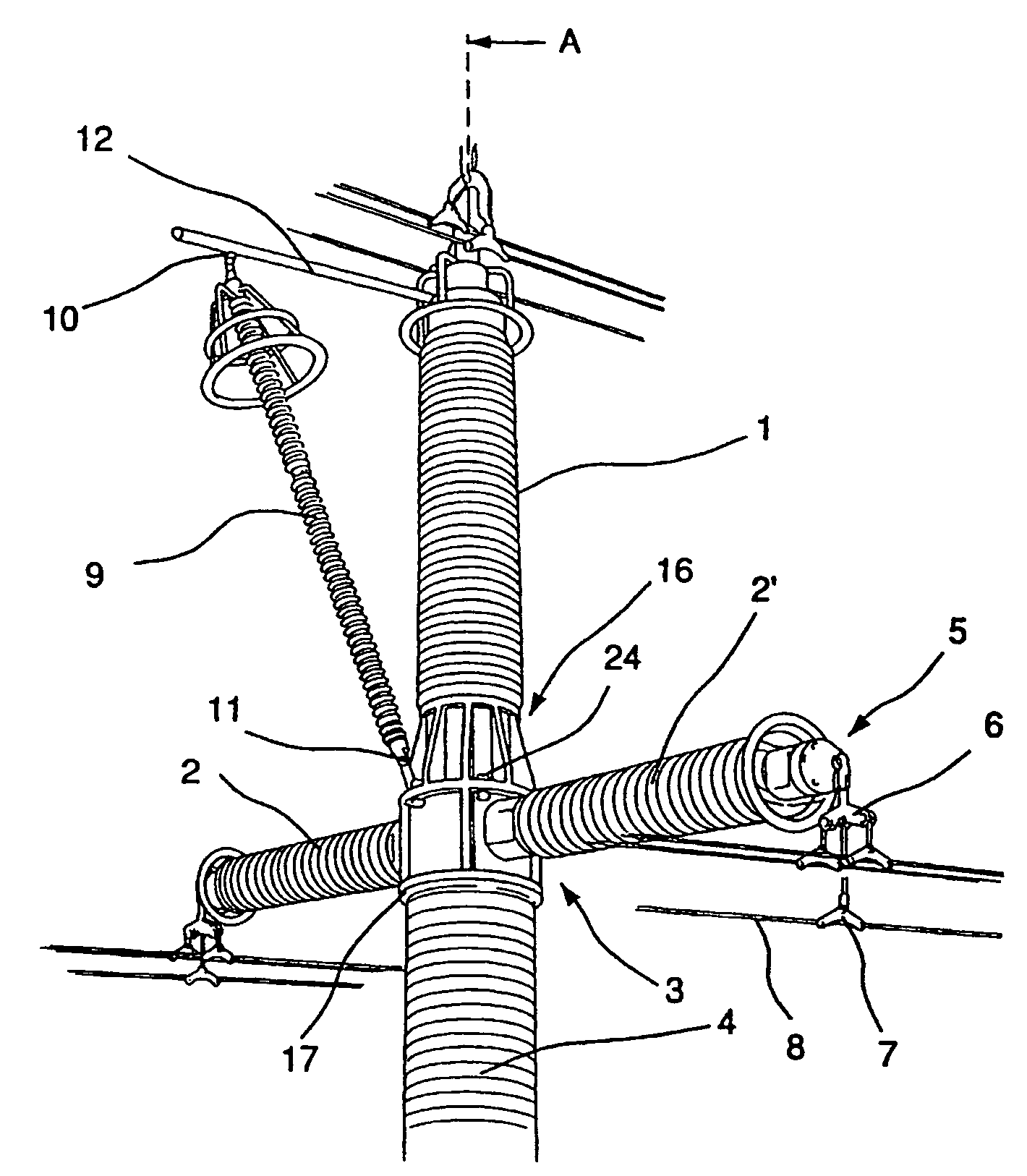
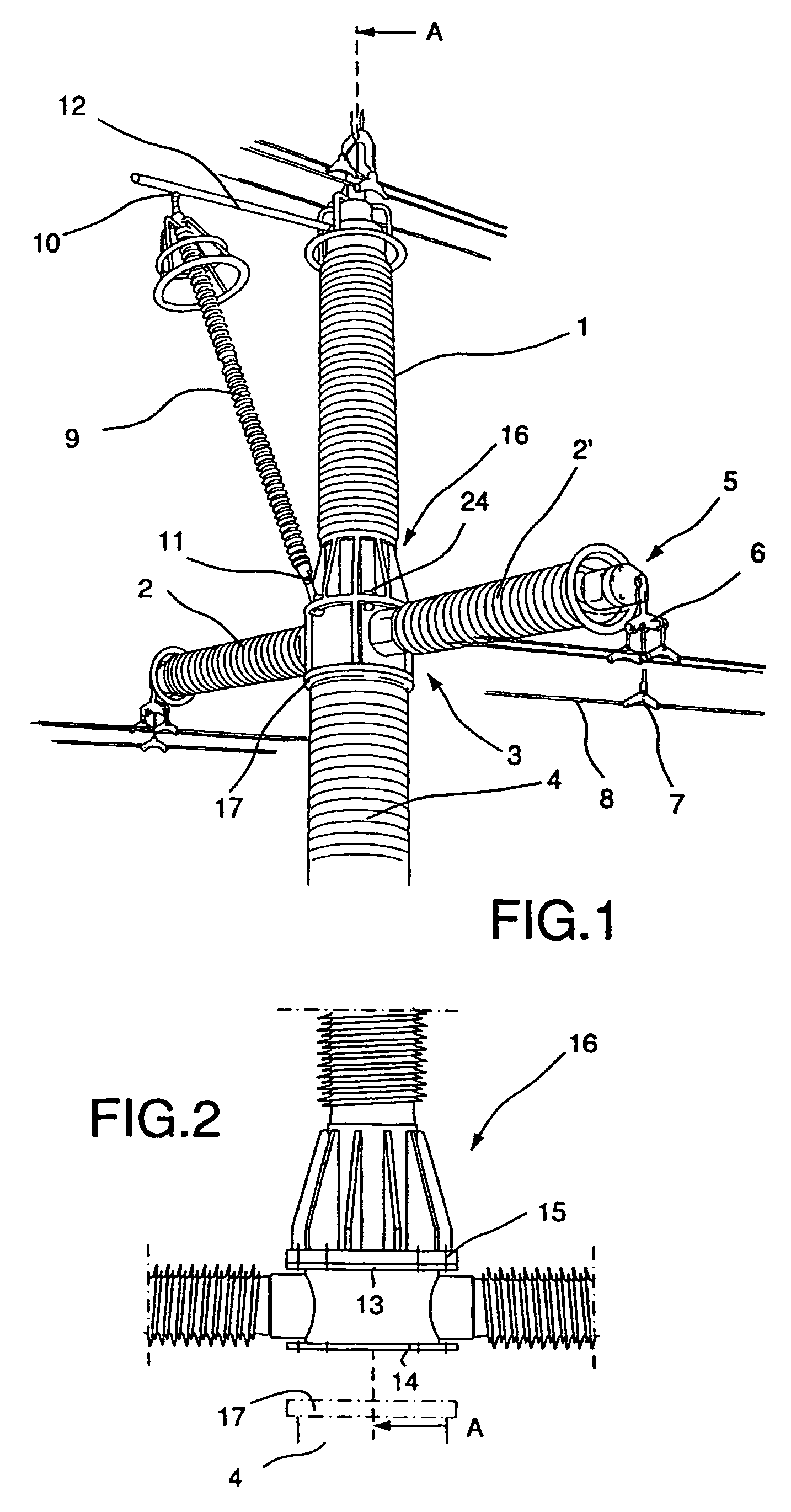
[0017]The present pole-top insulator in the embodiment shown in the drawings includes a first vertical tubular support arm 1 and a second and third designated 2 and 2′ respectively similar tubular supporting arms that arm oriented horizontally and located symmetrically on each side of a vertical plane of symmetry A and through the vertical tubular part. Each tubular and relatively continuous supporting arm 1, 2 and 2′ are made of some electrically insulating composite material, which can be made up of fiberglass reinforced epoxy. Suitable methods of manufacture include wet filament winding or injection moulding. Furthermore, the said tubular supporting arm can be monolithic or comprise several inter-joining tubular parts with a common centre axis. The tubular supporting arm then made is so designed that it exhibits both good insulating properties as well as such a high strength that it can be used as a self-supporting element with one or more phase leads or lines supported on its fr...


PUM


Abstract

A pole-top insulator for carrying overhead electrical cables on pole legs or similar supporting structures located along power lines. One or more self-supporting tubular supporting arms made of electrically insulating composite material to which supporting cables are fixed are arranged on the top end of the supporting structures. The tubular supporting arms are joined to the supporting structure via an intermediate center part that can be attached to the supporting structure from which the tubular supporting arms extend outwards.

Description

TECHNICAL FIELD[0001]The present invention concerns a pole-top insulator for carrying overhead electrical cables on pole legs or similar supports located along power lines and that includes one or more self-supporting tubular parts made of electrically insulating composite material to which supporting cables are fixed on the top end of the said supports.TECHNICAL STANDPOINT[0002]The means of carrying cables in high-tension power lines is usually achieved with the use of pylons in the form of steel framework structures, the legs and upper horizontal crossbar of which form the structural components. The insulators are supported by the crossbar in an essentially freely suspended manner, whereby the lines or phase leads are attached to the bottom of the inuslators. The said insulators are only used for insulation and to separate the cables from each other and the pole structure, however.[0003]One disadvantage with this known type of pole structure for power lines is that they require re...

Claims


Application Information

Patent Timeline
Patent Type & Authority Patents(United States)
IPC IPC(8): H02G7/00H02G7/20H02G7/05E04H12/24E04H12/00
CPCH02G7/053H02G7/20E04H12/24
Inventor LINDBERG, BJORNENGSTROM, JOHAN
Owner HITACHI ENERGY SWITZERLAND AG
Why Eureka
Eureka Blog
Learn More