
X-Y video camera support and positioning system

a video camera and positioning system technology, applied in the field of magnification viewing mechanism and system, can solve the problems of prohibitively expensive and difficult to maneuver, difficult to read and close, and cost several thousand dollars, and achieve the effect of convenient use and easy learning

Inactive Publication Date: 2005-11-15
REED CLAUDE R +1
View PDF10 Cites 5 Cited by
  • Summary
  • Abstract
  • Description
  • Claims
  • Application Information

AI Technical Summary

Benefits of technology

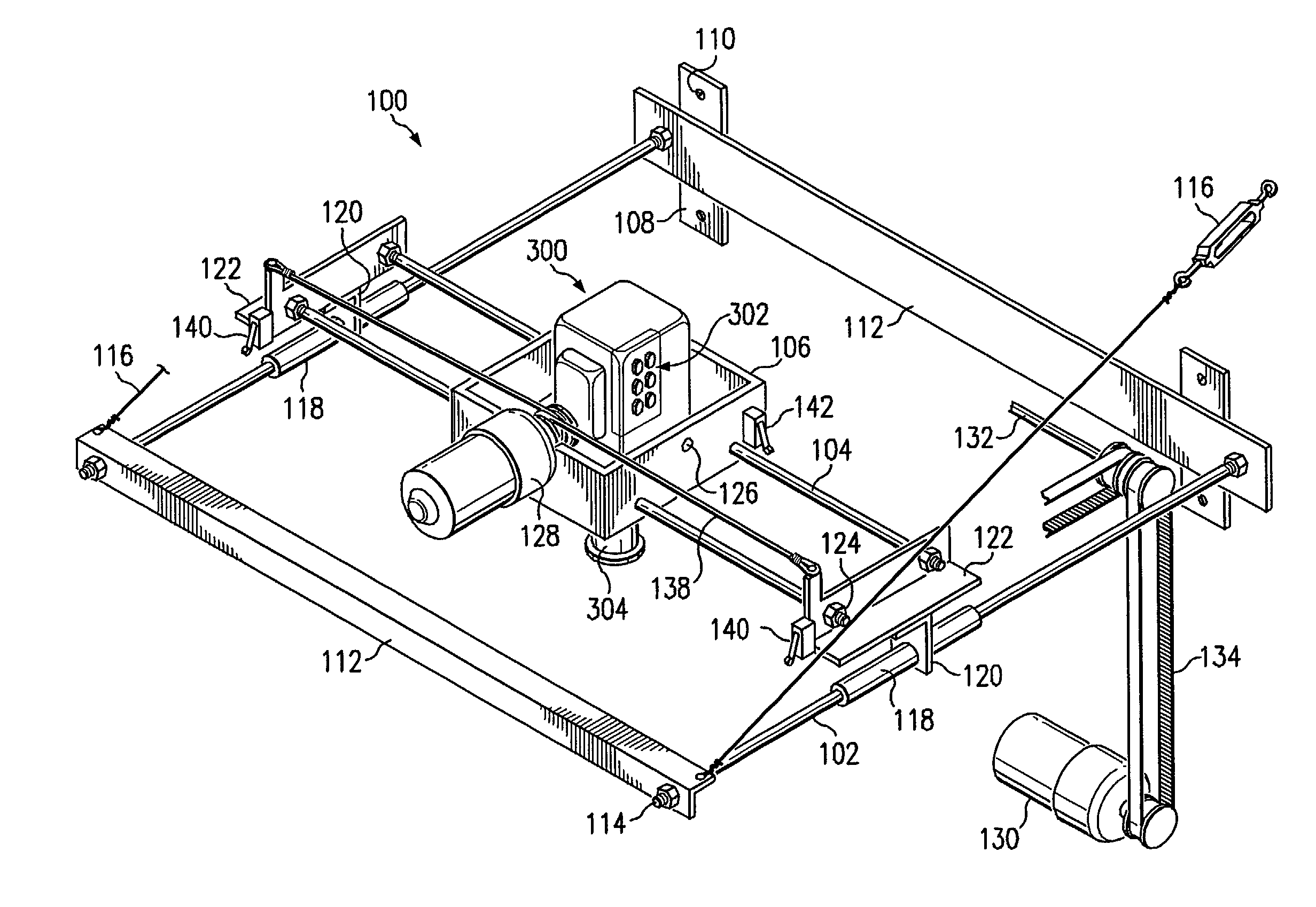
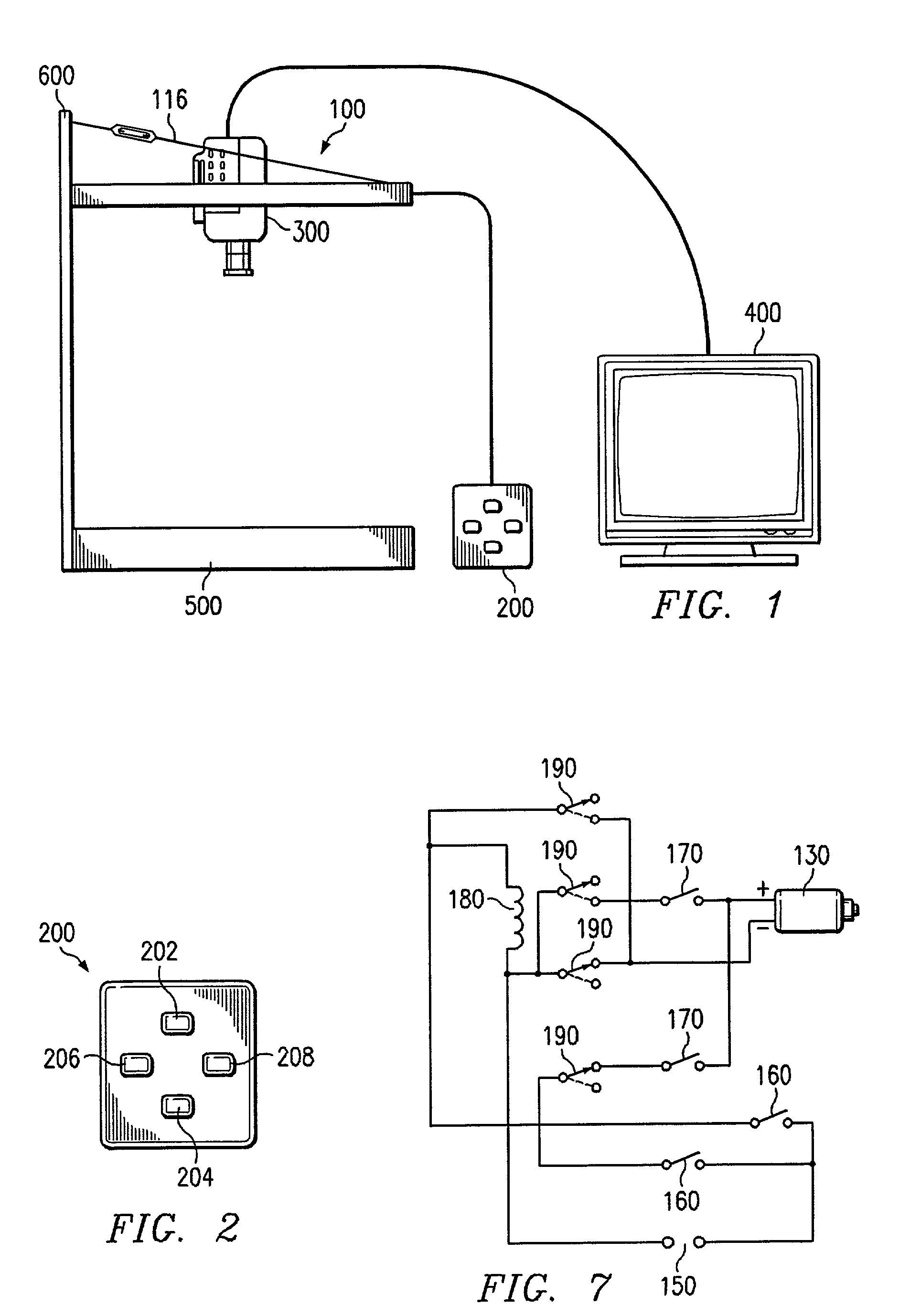
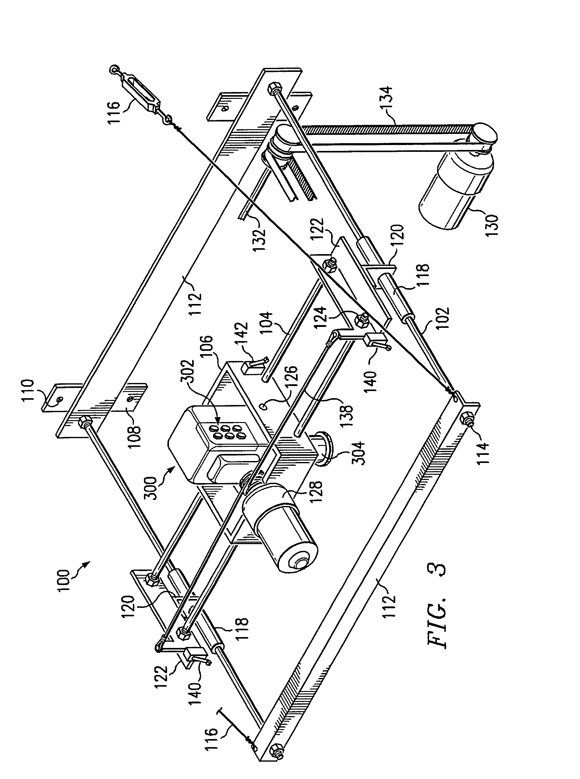
[0011]The present invention addresses the foregoing needs by providing an inexpensive system for vision enhancement that is extremely easy to use. A positioning device receives input from a four button control panel, which allows precise positioning of a video camera above a stage. The images from the video camera are output onto a monitor, where they are displayed. The camera can be moved left, right, up and down over the image, which is very natural and easy to learn. Instead of having to physically move an image under a stationary camera, the user can simply use up, down, left and right buttons to move the camera while the image stays stationary. With long enough cables or a remote control, the user does not have to be near the positioning device, potentially keeping it hidden in a corner of the room.

Problems solved by technology

But when both eyes are affected, reading and close up work can become difficult.
The problem with these systems, however, is that they are prohibitively expensive and hard to maneuver.
Some systems have portable headset systems and cost several thousand dollars.
Others are very inexpensive, but require the user to move the item of interest underneath the camera, which can be unnatural and hard to learn.

Method used


Image

  • X-Y video camera support and positioning system
  • X-Y video camera support and positioning system
  • X-Y video camera support and positioning system

Examples


Embodiment Construction

[0019]Referring now to the figures, a preferred embodiment of the system is shown in FIG. 1. FIG. 1 shows an X-Y video camera support and positioning system. The positioning device 100 receives input from a control panel 200, which allows precise positioning of a video camera 300 above a stage 500. Any type of material may be placed on the stage 500, but it is anticipated that items such as drawings, books, newspapers, magazines and pictures will be used most commonly. The images from the video camera 300 are output onto a monitor 400, where they are displayed. Examples of monitors are television sets and computer monitors. Magnification of the image is controlled by the video camera 300, and available magnifications will vary from model to model. In a preferred embodiment, stage 500 and positioning device 100 will be in a self-contained unit, connected by mounting wall 600. Preferably, the mounting wall will have an opening at the bottom so that large items, such as newspapers, wil...


PUM


Abstract

An X-Y video camera support and positioning system for enhancing viewing for persons with poor vision. The system includes a positioning device that receives input from a four button control panel, which allows precise positioning of a video camera above a stage. The images from the video camera are output onto a monitor, where they are displayed. The system is low cost and extremely easy to use.

Description

FIELD OF THE INVENTION[0001]The present invention relates generally to a magnified viewing mechanism and system, more particularly to a mechanism and system for magnifying materials too small for people with poor eyesight to otherwise see.BACKGROUND OF THE INVENTION[0002]Macular degeneration is the imprecise historical name given to a group of diseases that cause sight-sensing cells in the macular zone of the retina to malfunction or lose function and results in debilitating loss of vital central or detail vision.[0003]The retina contains an extraordinary photosensitive array of cells that line the back of the eye. The light falling onto these cells in the retina is transformed into electrical signals that are transmitted to the brain centers that process and interpret them.[0004]The most concentrated collection of photosensitive cells in the retina, including those that enable critical color and fine detail vision, are found in the Bulls-Eye center zone in an area called the macula...

Claims


Application Information

Patent Timeline
IPC IPC(8): H04N7/18
CPCH04N7/183
Inventor REED, CLAUDE R.REED, RICHARD C.
Owner REED CLAUDE R
Learn More