Heat transfer apparatus

a technology of heat exchanger and heat exchanger body, which is applied in the direction of light and heating apparatus, machines/engines, laminated elements, etc., can solve the problems of requiring considerable effort to ensure the long life of the recuperator, complex and difficult manufacturing of the recuperator, and scientists and engineers have spent a great deal of time and effort, and achieves less complicated construction and less cost.

Inactive Publication Date: 2005-11-22
WELLS FARGO BANK NAT ASSOC
View PDF6 Cites 15 Cited by
  • Summary
  • Abstract
  • Description
  • Claims
  • Application Information

AI Technical Summary

Benefits of technology

[0008]Another object of this invention is to provide a recuperator for a mircroturbine that is characterized as having fewer component parts than heretofore known recuperators and is less complicated to construct and is less expensive.

Problems solved by technology

Scientist and engineers have spent a great deal of time and effort for improving heat exchangers and particularly those used with microturbines.
Because the recuperator operates in a hostile environment, namely the relatively high pressure air discharging from the engine's compressor and the relatively hot exhaust (1000 degrees Fahrenheit (° F.)) discharging from the turbine, the manufacturing of the recuperator is complex and difficult and requires considerable effort to assure its long life.

Method used


Image

  • Heat transfer apparatus
  • Heat transfer apparatus
  • Heat transfer apparatus

Examples


Embodiment Construction

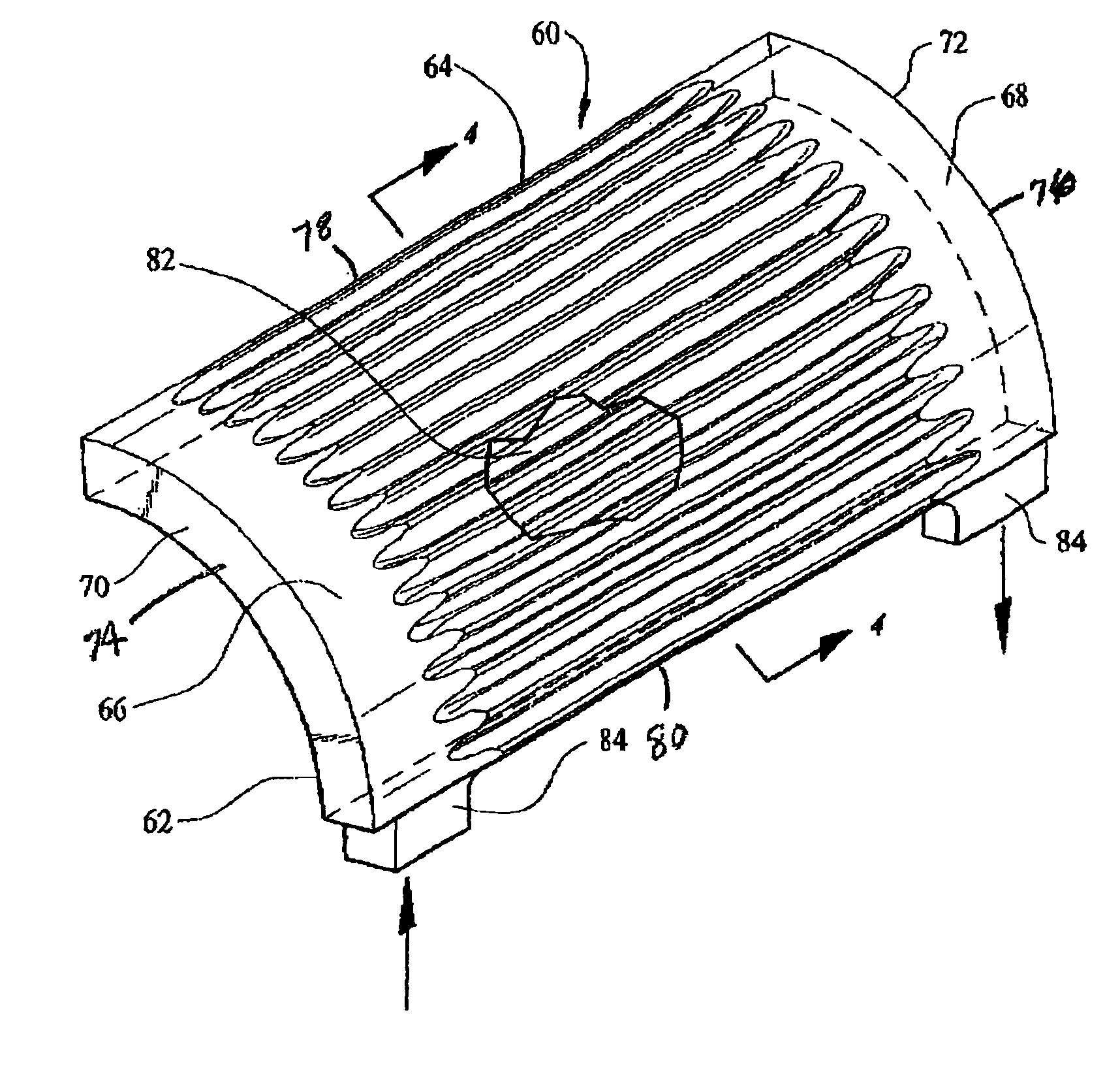
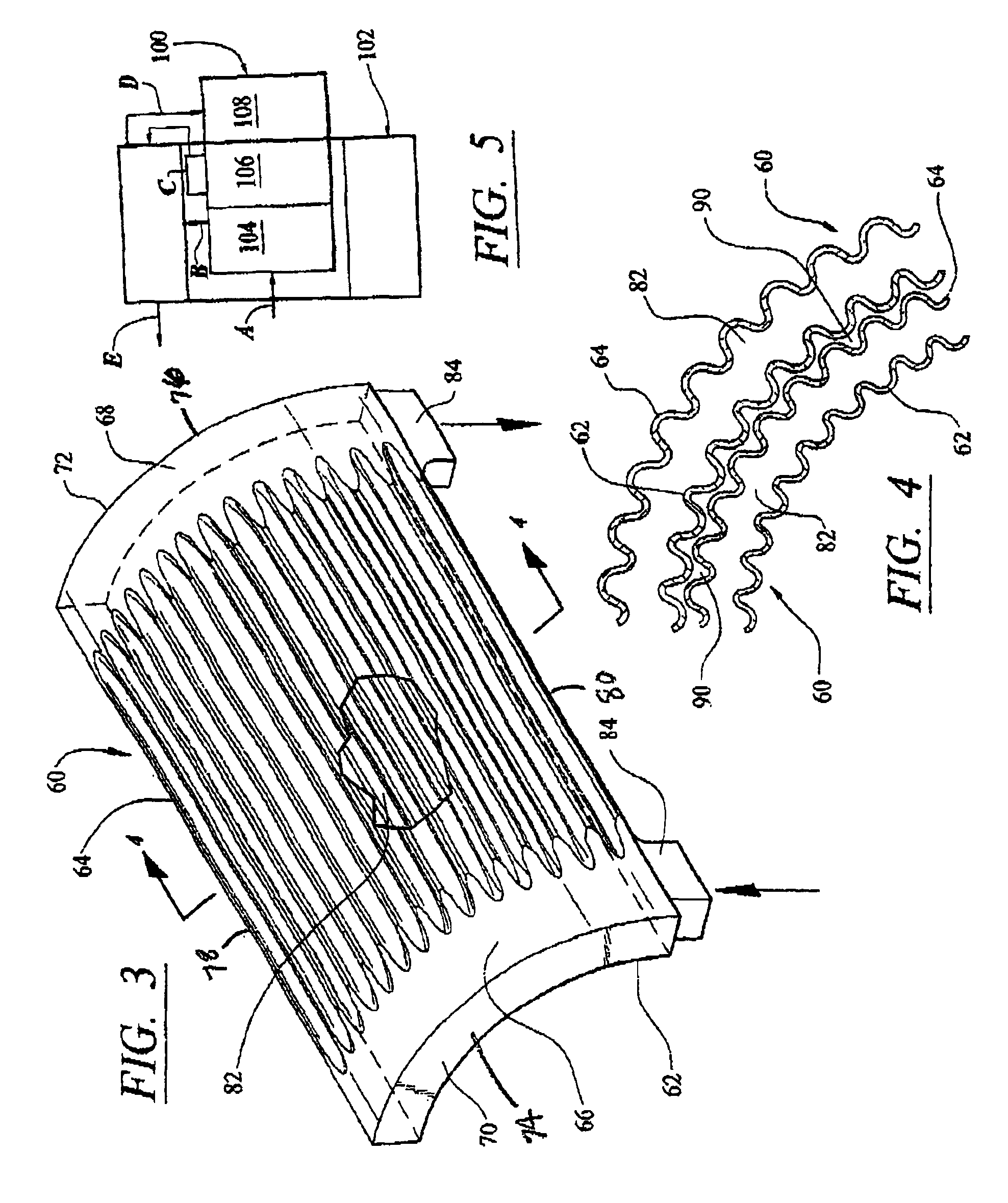
[0016]While the preferred embodiment is intended for use in the recuperator of a microturbine, as one skilled in this art will appreciate, the invention can be employed for other applications where it is necessary to transfer heat from one medium to another medium by indirect heat relation.

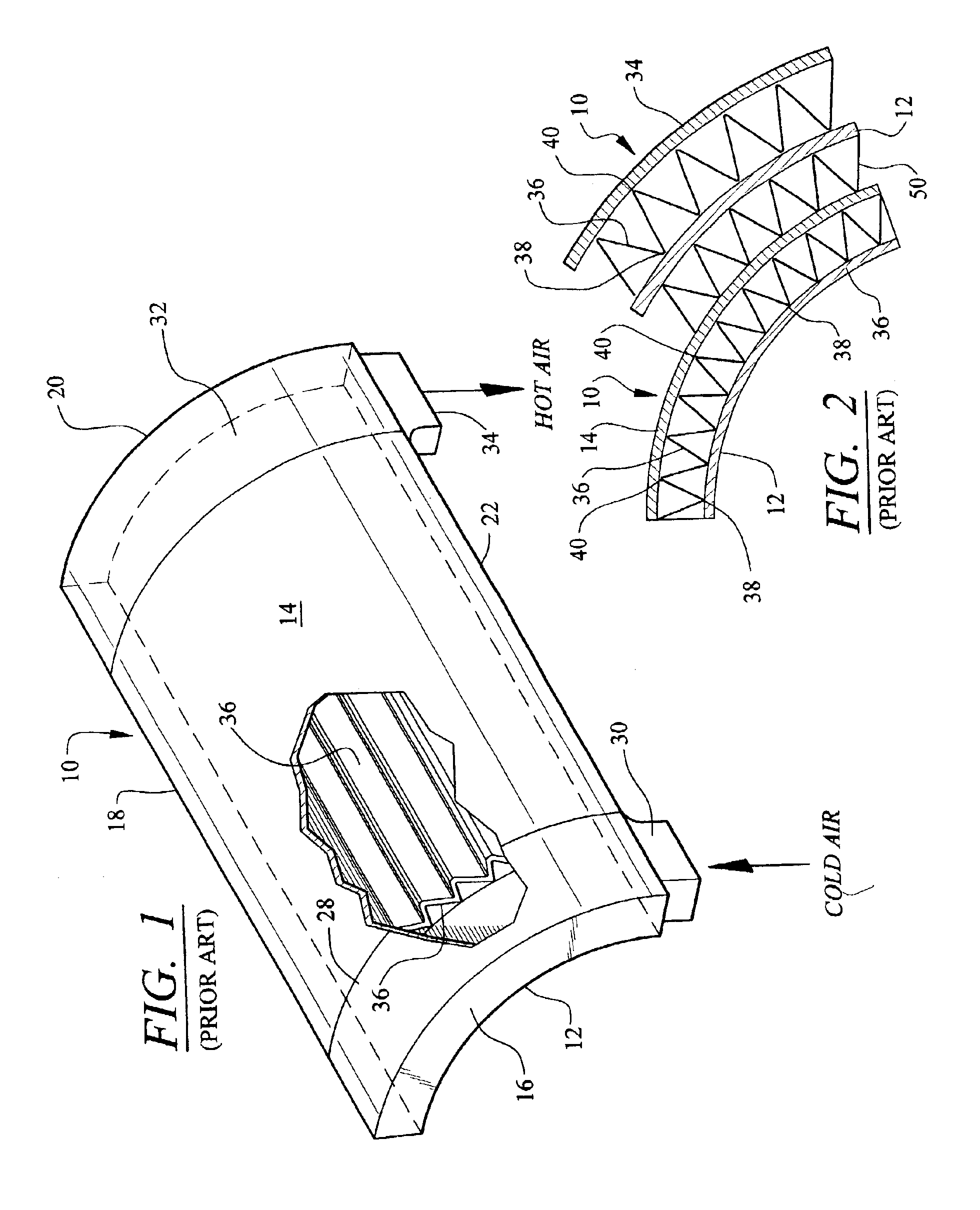
[0017]Reference is now made to FIGS. 1 and 2 disclosing a portion of the prior art recuperator or cell generally indicated by reference numeral 10 that is of the type that is disclosed in the aforementioned patent application and for further details thereof reference should be made thereto. Cell 10 comprises a fore wall 12 that is essentially a planar member shaped in a rectangle and being bent to define an involute shape. A contiguous aft wall 14 being parallel spaced therefrom with all the four edges of the fore wall 12 and aft wall 14 being bent or swaged at the edges 16, 18, 20 and 22 and suitably sealed to define a sealed hollow chamber 24. The space 26 at the left hand side of chamber 24 def...


PUM


Abstract

The annular recuperator for use with a microturbine includes an involuted shaped inner member with a portion thereof being corrugated and an involuted shaped outer member also with a portion thereof being corrugated and spaced therefrom to define a cell. The end portions of both the inner and outer members is planar and define a header for admitting and discharging the fluid flowing in the cell. The edges of the inner and outer members are sealed and an inlet and outlet are fluidly connected to the respective headers. The cells are circumferentially mounted side by side and abut each other but leaving sufficient space for another medium to flow through the space and be place in indirect heat exchange with the fluid flowing in the cell. The cells when mounted define an annular configuration so that compressor discharge air from the compressor of the microturbine flows through the cells and turbine discharge engine working fluid flows between the cells for preheating the compressor discharge air prior to being admitted into the combustor. The recuperator has utility as a heat exchanger for other applications.

Description

TECHNICAL FIELD[0001]This invention relates to heat exchangers and more particularly to heat exchangers that are adapted for use in an annular recuperator for a microturbine.BACKGROUND OF THE INVENTION[0002]This invention constitutes an improvement over the recuperator structure described and claimed in co-pending patent application Ser. No. 09 / 934,640 filed on Aug. 22, 2001 by William R. Ryan entitled “Recuperator For Use With Turbine / Turbo-alternator”, published and commonly assigned to the same assignee of this patent application and incorporated herein by reference. While the structure disclosed in the aforementioned patent application describes an annular recuperator for an annular combustor, the invention is essentially a heat exchanger that can be configured in other configurations such as annular, square, rectangular, etc.[0003]Scientist and engineers have spent a great deal of time and effort for improving heat exchangers and particularly those used with microturbines. As o...

Claims


Application Information

Patent Timeline
Patent Type & Authority Patents(United States)
IPC IPC(8): F02C7/08F28F3/00F28F3/04F28D9/00
CPCF02C7/08F28D9/0018F28F3/046
Inventor DEWIS, DAVID W.
Owner WELLS FARGO BANK NAT ASSOC
Why Eureka
Try Eureka