
Writing instrument, writing instrument cap and method of assembly of a writing instrument cap

a writing instrument and writing instrument technology, applied in the direction of writing connectors, printing, ink reservoir pens, etc., can solve the problems of inability to retain refills, writing tip rattling, and lower ink capacity, and achieve the effect of easy action of temporal tacking

Inactive Publication Date: 2005-11-22
MITSUBISHI PENCIL CO LTD
View PDF15 Cites 4 Cited by
  • Summary
  • Abstract
  • Description
  • Claims
  • Application Information

AI Technical Summary

Benefits of technology

[0021]According to the first aspect of the present invention, in a writing instrument, since the front barrel and the ink tank are formed integrally or as a one-piece structure as a refill (replacement pen element), the outside diameter of the ink tank can be enlarged by making the optimal use of the space inside the rear barrel, whereby it is possible to increase the ink capacity.
[0060]According to the nineteenth aspect of the present invention, the action of temporal tacking can be easily made.

Problems solved by technology

However, with the former writing instrument body configuration, looseness at the connection between the front and rear barrels causes unstable retention of the refill, giving rise to a problem of the writing tip rattling.
On the other hand, the latter writing instrument body configuration has no rattling problem at the writing tip because the front barrel and the point assembly are integrally formed, but has a problem of lower ink capacity.
However, this means increase in differential outside diameter between the front barrel and the attachment, causing the problem of the external appearance of the writing instrument body being spoiled.
Further, enlargement of the attachment results in exposure of the attachment beside the cap and the rear barrel, further degrading the external appearance of the writing instrument body.
However, in a case where a writing instrument body having the outer periphery printed with the maker name, trade name, model name and the like or covered with a thin film with these printed thereto is used for writing, the fitting portion of the cap rubs the outer periphery of the writing instrument body every time the cap is fitted to the rear end of the writing instrument body, so that there occurs the problem that the thin film may peel off from its rear end or the print may become faint and patchy.
However, these conventional configurations suffer from the problem of complexity in the shape of the writing instrument body and degradation of the external appearance.
Therefore, the fitter needs skill for the assembly work and also suffers from a hard burden on their fingers because a strong force should be applied to a small portion.
In anyway, it is difficult to automate these assembly steps.

Method used


Image

  • Writing instrument, writing instrument cap and method of assembly of a writing instrument cap
  • Writing instrument, writing instrument cap and method of assembly of a writing instrument cap
  • Writing instrument, writing instrument cap and method of assembly of a writing instrument cap

Examples


first embodiment

[The First Embodiment]

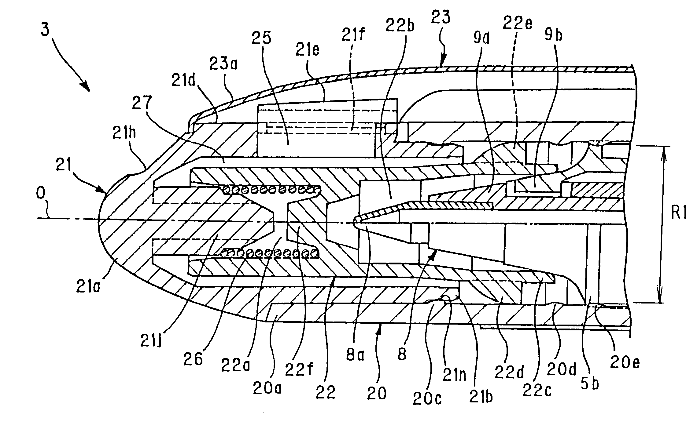
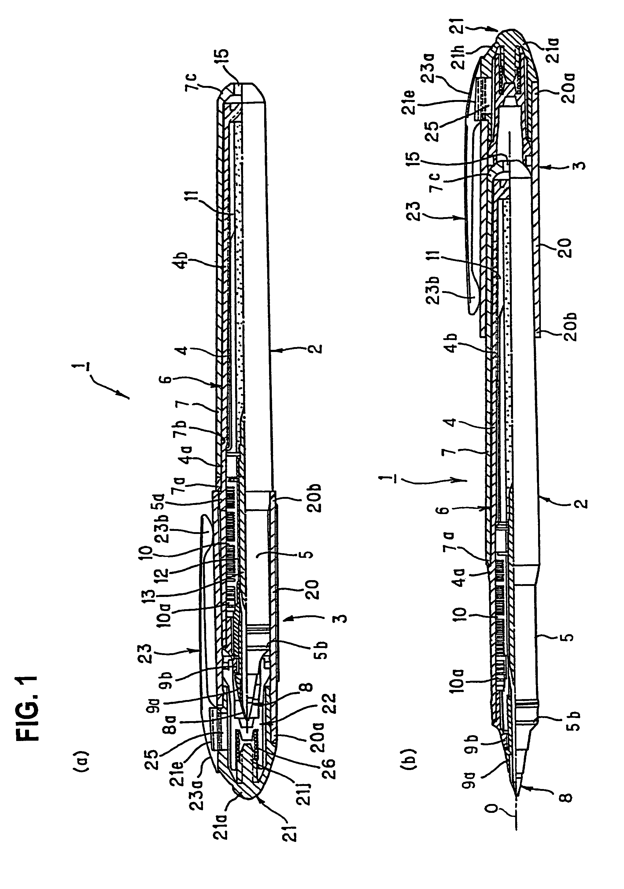
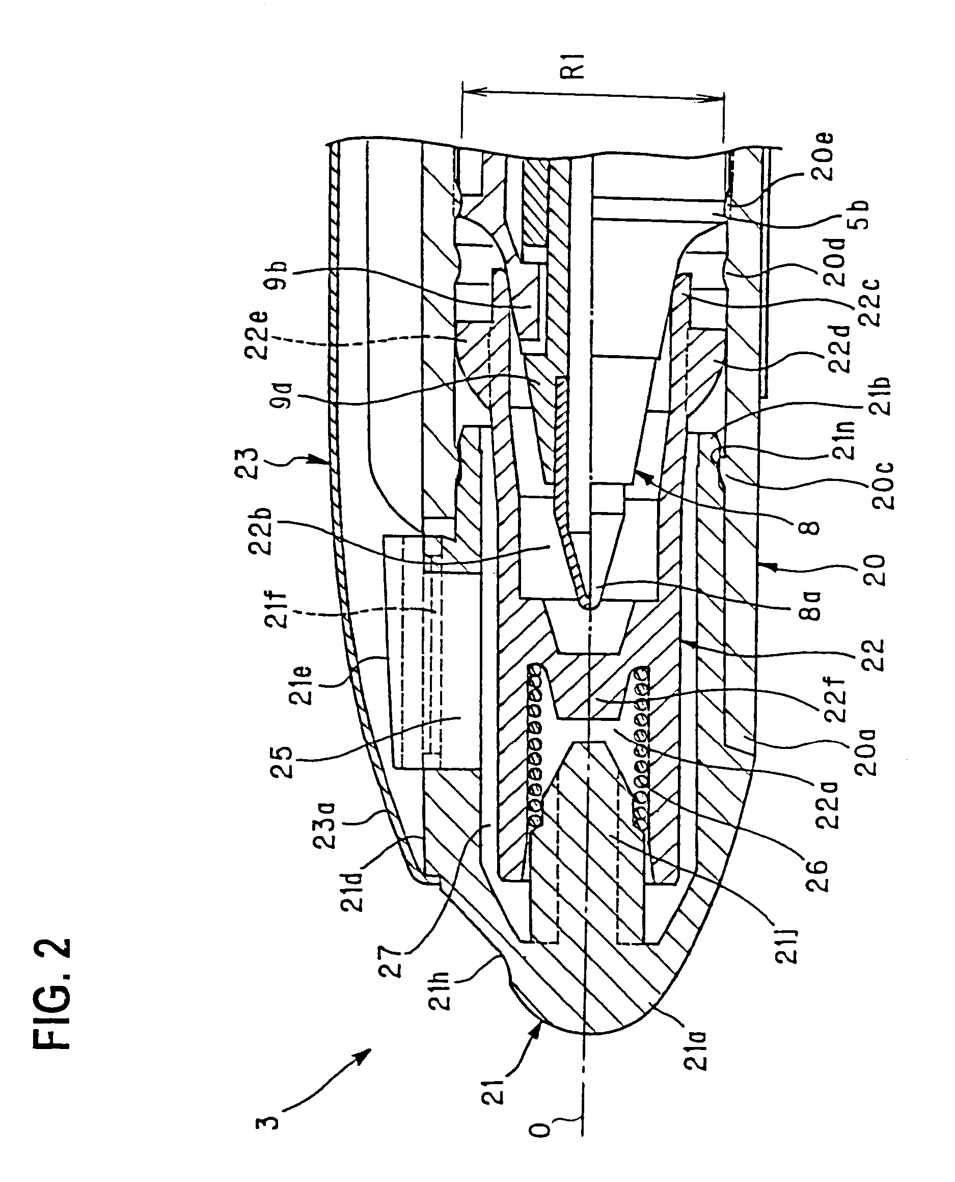
[0072]The writing instrument, writing instrument cap and assembly method of the writing instrument cap in accordance with the first embodiment of the present invention will hereinbelow be described in detail with reference to FIGS. 1 to 4.

[0073]A writing instrument 1 according to the present embodiment includes a writing instrument body 2 and a writing instrument cap 3 formed as a separate part, as shown in FIGS. 1(a) and (b).

[0074]The writing instrument body 2 is comprised of a refill portion 6 integrally formed of an ink tank 4 filled up with ink therein and a front barrel 5, a rear barrel 7 to which the refill portion 6 is fitted and a point assembly 8 provided in the front part of the refill portion 6.

[0075]The rear barrel 7 is adapted to accommodate the ink tank 4 and to be removably attached to the refill portion 6.

[0076]Ink tank 4 of refill portion 6 is the part accommodated by rear barrel 7, and front barrel 5 is the part located on the point assembly 8...

second embodiment

[The Second Embodiment]

[0149]The writing instrument, writing instrument cap and assembly method of the writing instrument cap into the writing instrument, in accordance with the second embodiment of the present invention will hereinbelow be described in detail with reference to FIGS. 5 to 11.

[0150]As shown in FIG. 5, writing instrument 31 is comprised of a writing instrument cap A and a writing instrument body B.

[0151]The writing instrument body B is formed of a barrel cylinder 35 and a cylindrical exterior body 36, wherein barrel cylinder 35 is inserted into cylindrical exterior body 36 and threaded portions 35d and 36b are screw fitted to each other.

[0152]Barrel cylinder 35 has a front opening 35a in which a point assembly 34 having a writing point 32 supported by a holder 33 is fitted, and incorporates an ink collector portion 35b in the front half adjacent to the point assembly 34 side and an ink tank portion 35c in the rear half behind the front half. A threaded portion 35d is ...


PUM


Abstract

A writing instrument includes a front barrel and an ink tank. When, with a rear barrel for accommodating the ink tank removably fitted on the ink tank, a cap formed to cover the front barrel is fitted on the front barrel, the cap is positioned and fastened by abutment of the opening end of the cap. The cap has a hollow for accommodating a point assembly. The inside diameter of the hollow exceeds the outside diameter of the front barrel and the outside diameter of a rear end of the rear barrel. A barrel hold is formed along the circumference on the inner wall portion of the cap, so that the barrel hold grips the outer periphery of the rear end of the rear barrel. A guide portion is formed on the inner wall portion of the cap, closer to the front side than the barrel hold, to restrain over insertion of the rear end of the rear barrel into the cap. A writing instrument cap is assembled of a cap body and a clip by engaging an engaging portion formed on the cap body and a hooking portion formed in the clip, and is constructed so that engagement becomes gradually tight as the clip is slid along the axis from a tacking position.

Description

TECHNICAL FIELD[0001]The present invention relates to a writing instrument such as a ball-point pen, fountain pen and the like, a writing instrument cap and a method of assembly of a writing instrument cap.BACKGROUND ART[0002]Generally, for writing instruments such as oil-based ball-point pens, water-based ball-point pens, a removable cap for protecting the front end of the writing part by enclosing it when unused is provided.[0003]Particularly, in some kinds of writing instruments, in order to prevent ink at the writing part from drying, the tip part is hermetically enclosed by the cap so that the part can be isolated from the outside air.(Background Art 1)[0004]As one of the conventionally known writing instrument configurations, a refill (replacement pen element) which is formed of a point assembly and an ink tank by engaging one with the other, is accommodated, on its tip side, into a front barrel, and on its ink tank side, into a rear barrel, forming an joined writing instrumen...

Claims


Application Information

Patent Timeline
Patent Type & Authority Patents(United States)
IPC IPC(8): B43K29/00B43K23/00B43K23/12
CPCB43K7/005B43K8/003B43K23/12B43K23/124B43K29/00
Inventor FURUKAWA, KAZUHIKOSANO, YOJIRO
Owner MITSUBISHI PENCIL CO LTD
Learn More