Circuit continuity and function monitor

a function monitor and circuit continuity technology, applied in the direction of discharge tube/lamp details, instruments, transportation and packaging, etc., can solve the problems of fiber optic cables that are difficult to run and maintain in the operating position, affecting the safety of vehicles, and pulling thousands of motorists

Inactive Publication Date: 2005-11-22
JEWELL DAN J +1
View PDF10 Cites 26 Cited by
  • Summary
  • Abstract
  • Description
  • Claims
  • Application Information

AI Technical Summary

Benefits of technology

[0004]It is an object of this invention to improve safety in vehicles and other equipment employing low voltage light bulbs. It is an object of this invention to disclose an improved apparatus for monitoring low voltage light bulbs. It is an object of this invention to disclose an apparatus which continuously monitors individual light bulbs when the bulb is lit and when the bulb is switched off. It is yet a further object of this invention to disclose an apparatus which discloses the location of a burnt out light bulb. The monitoring apparatus may include an audio alarm to ensure that a driver is aware of the problem.

Problems solved by technology

Hundreds of thousands of motorists are pulled over annually because a light bulb is burnt out on their vehicle.
These unscheduled and unexpected inspections frequently lead to more serious fines than those for having a burnt out light bulb.
Last year Honda recalled 440,000 cars because of the safety hazard resulting from headlamps going out and the driver being unaware of the problem.
But these fiber optic cables are difficult to run and maintain in operative position.

Method used


Image

  • Circuit continuity and function monitor
  • Circuit continuity and function monitor
  • Circuit continuity and function monitor

Examples


Embodiment Construction

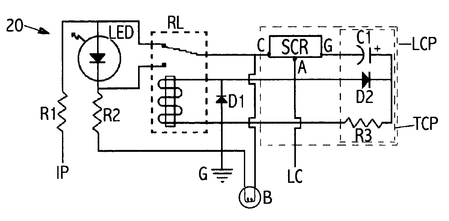
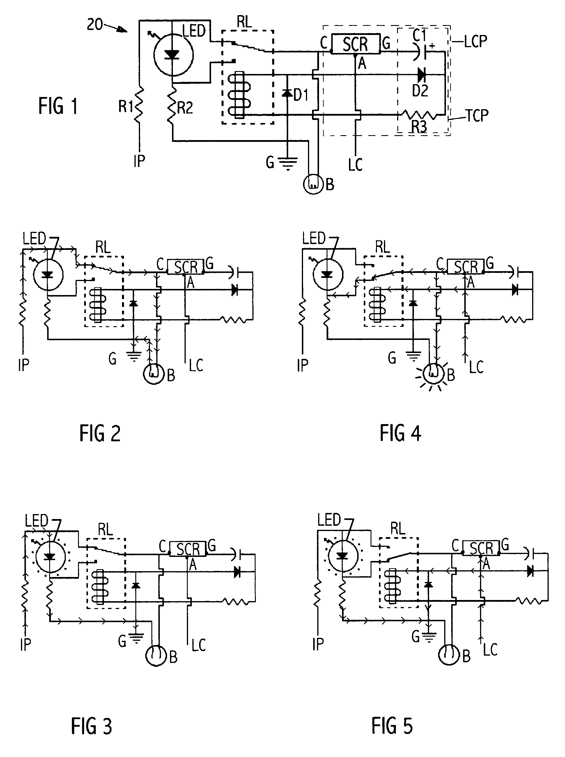
[0016]Turning now to the drawings and more particularly to FIG. 1 we have a schematic view of a light bulb monitoring circuit 20. Switched power Lc, originally supplied to the light bulb B is fed to the circuit 20. The light bulb B, as well as ignition power IP, a switched light power control line Lc, and ground G are connected to the circuit 20. A method of monitoring the operability of a light bulb B, both while lit and unlit, comprises the steps of: providing a circuit 20 containing a light emitting diode LED, a relay RL and a latching circuit portion LCP, said latching circuit portion LCP configured to remain latched thereby applying power to the bulb B and the relay RL only when the bulb B is switched on and lit, and said relay RL having a pair of contacts connected to provide an alternative path of minimal resistance to ground for low voltage applied to an incoming side of the LED, and said relay RL also having an additional pair of contacts which when closed allow voltage to ...


PUM


Abstract

A circuit to monitor electrical continuity through a light bulb when the light bulb is switched off, and to monitor proper functioning of the light bulb when the bulb is switched on. The circuit comprises a LED, a relay and a latching circuit portion, the latching circuit portion configured to remain latched thereby applying power to the bulb and the relay only when the bulb is switched on and lit, and the relay having a pair of normally closed contacts connected to provide an alternative path of minimal resistance to ground for low voltage applied to an incoming side of the LED, and the relay also having a pair of normally open contacts which when closed allow voltage to be applied to the outgoing side of the LED, thereby resulting in the LED lighting when and only when, the light bulb is broken. Most preferably the latching portion of the circuit comprises a silicone controlled rectifier having a trigger circuit portion configured to pulse the gate when a switched light power control line is energized. The switched light power control line is connected to the anode and a coil of the relay, and the cathode is connected to one of the normally closed contacts of the relay and to the light bulb.

Description

FIELD OF THE INVENTION[0001]This invention relates to testing of low voltage light bulbs. More particularly this invention relates to a circuit especially designed for a vehicle. The circuit monitors electrical continuity through a light bulb when the light bulb is switched off. The circuit alternatively monitors proper functioning of the light bulb when the bulb is switched on.BACKGROUND OF THE INVENTION[0002]Hundreds of thousands of motorists are pulled over annually because a light bulb is burnt out on their vehicle. These unscheduled and unexpected inspections frequently lead to more serious fines than those for having a burnt out light bulb. Last year Honda recalled 440,000 cars because of the safety hazard resulting from headlamps going out and the driver being unaware of the problem.[0003]Some luxury vehicle manufacturers have ran fiber optic cable from individual lights to a location visible to the driver. But these fiber optic cables are difficult to run and maintain in ope...

Claims


Application Information

Patent Timeline
Patent Type & Authority Patents(United States)
IPC IPC(8): B60L1/00B60L1/14G01R31/02H01H31/00H01H31/02H01J1/00H01J1/60G01R31/44H01K3/30
CPCG01R31/44H01K3/305
Inventor JEWELL, DAN J.JEWELL, JUDITH D.
Owner JEWELL DAN J
Why Eureka
Try Eureka