Polarization correlation signal processing for radiometers, ladars, and radars

a technology of polarization correlation and signal processing, applied in the direction of instruments, measurement devices, and using reradiation, can solve problems such as moving parts

Inactive Publication Date: 2005-11-22
SEC OF THE ARMY +1
View PDF9 Cites 25 Cited by
  • Summary
  • Abstract
  • Description
  • Claims
  • Application Information

AI Technical Summary

Problems solved by technology

The disadvantage of this approach is that it involves moving parts, since these optical components must be placed successively in the optical path.

Method used


Image

  • Polarization correlation signal processing for radiometers, ladars, and radars
  • Polarization correlation signal processing for radiometers, ladars, and radars
  • Polarization correlation signal processing for radiometers, ladars, and radars

Examples


Embodiment Construction

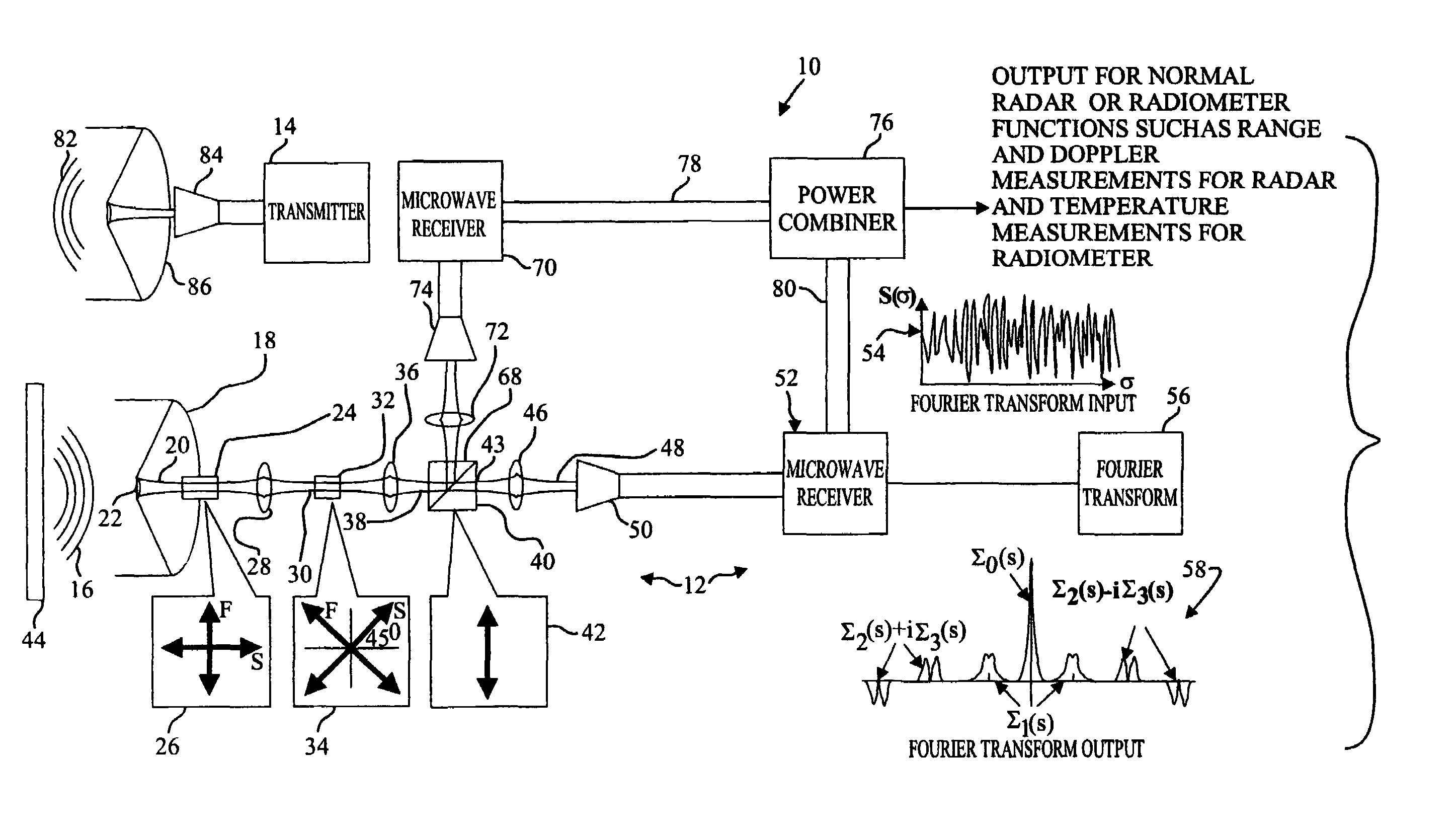
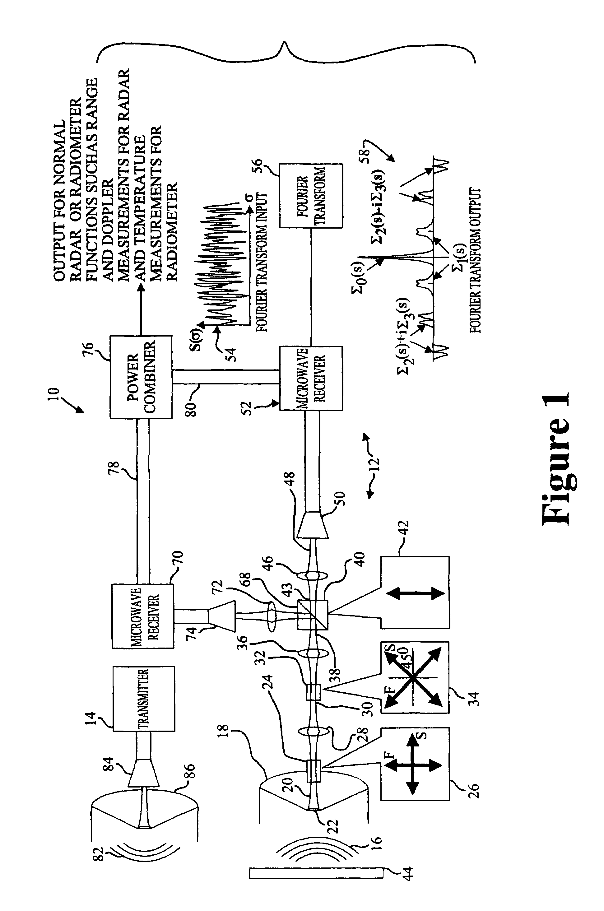
[0023]One embodiment of the present invention concerns a device and a method for comparing a polarization signature of a target scene within a radar return signal to a known polarization signature in just one radar coherent processing interval. This approach is based on the principle that a broadband electromagnetic wave propagating through cascaded birefringent elements has different polarization vectors rotated by differing amounts depending on the original state of polarization and frequency. If the resulting or modulated signal is then propagated through a linear polarizer serving as an analyzer, a spectrum results that is a function of polarization state relative to frequency. This spectrum may then be compared to those of known targets in a comparator or a correlator, thereby resulting in possible target identification where the correlation coefficient is sufficiently high. In conjunction with patent application Ser. No. 10 / 341,151 to McMillan, et al., filed Jan. 13, 2003, if ...


PUM


Abstract

A correlating polarimeter is provided for correlating a received waveform of a wideband electromagnetic signal with a predetermined waveform. The correlating polarimeter may include a first antenna for receiving an electromagnetic signal and a modulator interconnected with the first antenna for modulating the electromagnetic signal whereby a modulated electromagnetic signal results which contains a different polarization state for each frequency of the electromagnetic signal with the amplitude of each frequency component of the modulated electromagnetic signal being a function of the particular polarization state of each frequency component of the electromagnetic signal. The correlating polarimeter may also include a linear polarizer that may be configured to pass a first predetermined polarization of the modulated electromagnetic signal through a first output thereof, a first receiver for receiving and demodulating the electromagnetic signal from the linear polarizer and outputting a received waveform and a correlator operatively interconnected with the first receiver and being configured to compare the received waveform to a predetermined waveform and output a correlation indicator.

Description

CROSS REFERENCE TO RELATED APPLICATION[0001]This application is a continuation-in-part of U.S. patent application Ser. No. 10 / 341,151, filed Jan. 13, 2003 and entitled “A Device and Method for Determining All Components of the Stokes Polarization Vector within a Radar Signal,” now U.S. Pat. No. 6,762,713, granted Jul. 13, 2004.BACKGROUND OF THE INVENTION[0002]1. Field of the Invention[0003]The present invention relates to devices and methods for comparing or correlating a state of polarization of an electromagnetic wave to a known library of such polarization states and, more particularly, to applications where the comparison of the state of polarization of an electromagnetic wave are employed, such as for target discrimination.[0004]2. Related Art[0005]Identifying the state of polarization of an electromagnetic wave by determining the Stokes polarization vector components of the wave is known. In particular, an electromagnetic wave, such as a spectral band of light, or of electroma...

Claims


Application Information

Patent Timeline
Patent Type & Authority Patents(United States)
IPC IPC(8): G01S7/02G01S7/40
CPCG01S7/024G01S7/4004
Inventor MCMILLAN, ROBERT W.HOLDER, ERNEST J.
Owner SEC OF THE ARMY
Why Eureka
Try Eureka