Method of estimating and correcting camera rotation with vanishing point location

a technology of vanishing point and camera rotation, applied in the field of image processing, can solve the problems of difficult to hold a camera level, small rotations are generally unintentional, and detecting a small amount of camera rotation, so as to improve the method of correction

Inactive Publication Date: 2005-11-22
INTELLECTUAL VENTURES FUND 83 LLC
View PDF7 Cites 53 Cited by
  • Summary
  • Abstract
  • Description
  • Claims
  • Application Information

AI Technical Summary

Benefits of technology

[0012]The present invention has an advantage of improving the method of correcting for small angles of camera rotation, i.e. camera tilt.

Problems solved by technology

Many photographers find it very difficult to hold a camera level when capturing a photograph.
These small rotations are generally unintentional and may occur because conventional consumer cameras are lightweight, for example, the popular Single-Use cameras.
Whereas, this sensor can enable one to determine the orientation or format of a captured image, it cannot lead to detecting a small amount of camera rotation.
However, this is not always the case.
The Lutton method requires a great deal of processing and may be computationally costly.
However, this solution cannot lead to compensating for camera rotation about the optical axis.
Therefore, pending U.S. application Ser. No. 09 / 281,574 is limited to describing a method of correction exclusively unique to the problem of camera rotation about the x-axis.

Method used


Image

  • Method of estimating and correcting camera rotation with vanishing point location
  • Method of estimating and correcting camera rotation with vanishing point location
  • Method of estimating and correcting camera rotation with vanishing point location

Examples


Embodiment Construction

[0020]In the following description, the present invention will be described in the preferred embodiment as a method. Those skilled in the art will readily recognize that the equivalent of such a method may also be constructed as hardware or software within the scope of the invention.

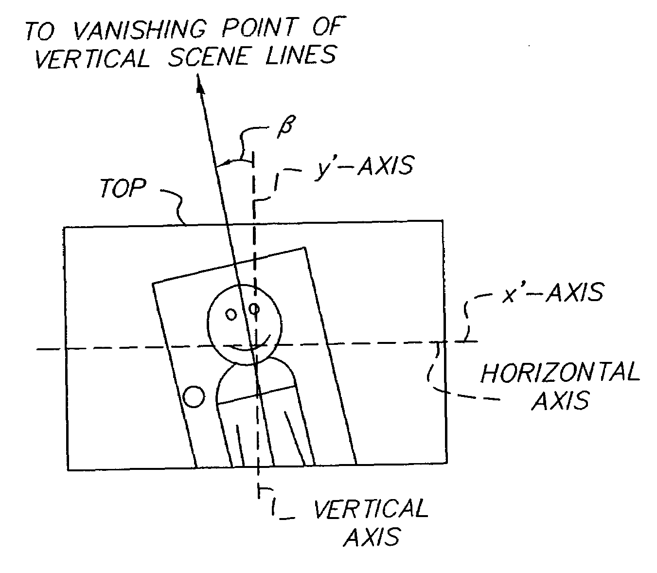
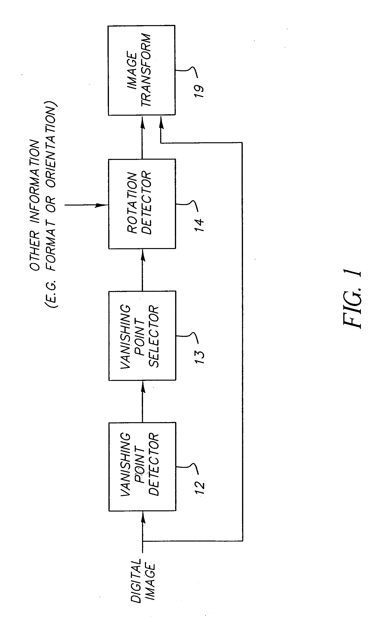
[0021]FIG. 1 shows a block diagram of the present invention. The purpose of the present invention is to estimate the amount of rotation of a camera relative to the scene at the time of image capture, based upon a digitized representation of an image. The source of the digitized image is irrelevant. The digitized image may be a scan of a film negative, a scan of a photograph, or an image captured with a digital camera. It should be well understood that in cases where the digitized image is a scan of a hardcopy image that the rotation of the digitized image corresponds to the rotation of the source image. That is, if a photograph was captured with a camera that was tilted by β degrees, then the correspondi...


PUM


Abstract

A method of generating an image transform for modifying a digital image, that includes the steps of: detecting a vanishing point related to the selected image; determining a preferable vanishing point location, and generating an image transform based on the vanishing point location and the preferable vanishing point location. In another embodiment, the present invention provides a method for detecting an amount of rotation between the vertical axes of a scene and an image of the scene, that includes the steps of: detecting a set of vanishing points related to the image; selecting a set of vanishing points corresponding to a vertical axis of the scene based on a predetermined criteria; and using the selected vanishing points to detect the rotation of the image.

Description

CROSS REFERENCE TO RELATED APPLICATIONS[0001]Reference is made to U.S. Provisional Ser. No. 60 / 192,400, filed Mar. 27, 2000, entitled Correction of Small Image Rotations Based on Vanishing Point Detection by Andrew C. Gallagher.FIELD OF THE INVENTION[0002]The invention relates generally to the field of image processing. More specifically, the invention relates to estimating and correcting for unintentional rotational camera angles that occur at the time of image capture, based upon the captured image's corresponding location of its vanishing points. Furthermore, the invention relates to image warping; the process of warping an image in a manner that causes the vanishing points of the image to relocate.BACKGROUND OF THE INVENTION[0003]Conventional consumer cameras (both film and digital) capture an image having a rectangular imaging area. For cameras using 35 mm film, the horizontal dimension of the imaging area is approximately 36 mm and the vertical dimension of the imaging area is...

Claims


Application Information

Patent Timeline
Patent Type & Authority Patents(United States)
IPC IPC(8): G06K9/32G06T7/00G06V10/147H04N5/232
CPCG06K9/209G06K9/3208G06T7/004H04N5/23248H04N5/23254H04N5/23258G06T7/70G06V10/242G06V10/147H04N23/6811H04N23/68H04N23/6812
Inventor GALLAGHER, ANDREW C.
Owner INTELLECTUAL VENTURES FUND 83 LLC
Why Eureka
Try Eureka