Remanufacturing method for toner supply container

a technology remanufacturing method, which is applied in the direction of instruments, electrographic process equipment, optics, etc., can solve the problems of easy scattering, loss of commercial value of toner supply container, and difficulty in automatic discharge of toner by gravity alone, and achieves the effect of simple method

Inactive Publication Date: 2005-11-22
CANON KK
View PDF21 Cites 40 Cited by
  • Summary
  • Abstract
  • Description
  • Claims
  • Application Information

AI Technical Summary

Benefits of technology

[0019]The primary object of the present invention is to provid

Problems solved by technology

Toner is in the form of an extremely small particle, being therefore prone to scatter.
In the case of the above described type of toner supplying method, it is difficult for toner be automatically discharged by gravity alone.
In the case of the above described toner supply container, the toner therein is continuously consumed during

Method used


Image

  • Remanufacturing method for toner supply container
  • Remanufacturing method for toner supply container
  • Remanufacturing method for toner supply container

Examples


embodiment 1

(Embodiment 1)

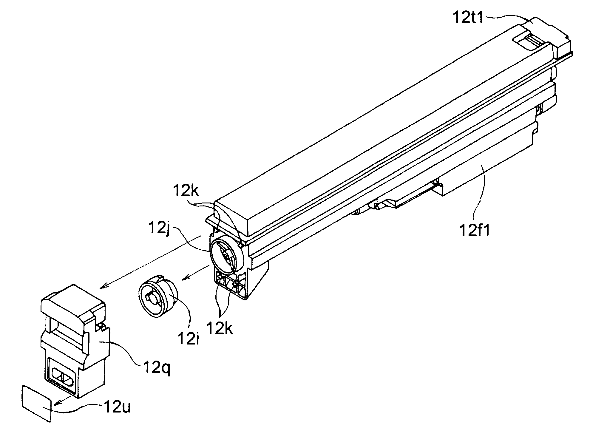
[0164]A remanufacturing method for the toner supply container 12 comprising the capping member 12i for sealing the toner inlet 12j and the capping member covering member 12q for covering the capping member 12i, and removably mountable in the main assembly of an image forming apparatus, characterized in that it comprises:

[0165]a first step in which the capping member covering member 12q is removed from the main assembly of the toner supply container, by destroying or removing the portions of the toner supply container, which were thermally deformed (thermally crimped) to attach the capping member covering member 12q to the main assembly of the toner supply container;

[0166]a second step in which the capping member 12i is removed to open the toner inlet 12j;

[0167]a third step in which developer (toner, or mixture of toner and carrier) is filled into the toner supply container through the toner inlet 12j;

[0168]a fourth step in which the toner inlet 12j is sealed with the...

embodiment 2

(Embodiment 2)

[0170]A remanufacturing method, in accordance with the first embodiment of the present invention, for a toner supplying container having a member (label 12u) covering the portions of the capping member covering member 12q, which are in contact with the thermally deformed projections of the toner supply container frame, characterized in that in the first step, the label 12u is peeled to expose the thermally deformed portion, and then, the thermally deformed portion is removed.

embodiment 3

(Embodiment 3)

[0171]A remanufacturing method, in accordance with the first or second embodiment of the present invention, for a toner supply container, the capping member covering member 12q of which are solidly attached to the main assembly of the toner supply container by thermally deforming one or more portions of the main assembly of the toner supply container, characterized in that in the first step, the thermally deformed portions are removed to remove the capping member covering member 12q from the main assembly of the toner supply container.


PUM


Abstract

A remanufacturing method for a developer supply container detachably mountable to a main assembly of an image forming apparatus, the developer supply container including a frame, a developer accommodating portion for accommodating a developer to be used by a developing device of the image forming apparatus, a developer filling opening for filling the developer into the developer accommodating portion, a capping member for closing the developer filling opening, and a cap covering member covering the capping member, the cap covering member being fixed by welding to the frame, the remanufacturing method including a cap covering member dismounting step of dismounting the cap covering member from the frame by separating cap covering member from the frame at a welded portion; a capping member dismounting step of dismounting the capping member to open the developer filling opening; a developer filling step of filling the developer with the developer filling opening; a capping member mounting step of closing the developer filling opening by a capping member; a cap covering member mounting step of mounting the cap covering member to the frame.

Description

FIELD OF THE INVENTION AND RELATED ART[0001]The present invention relates to a method for remanufacturing a developer supply container removably mountable in the main assembly of an image forming apparatus.[0002]Toner in the form of a micro-particle has long been used as the developer for an electrophotographic image forming apparatus. Here, an electrophotographic image forming apparatus means an apparatus which forms an image on recording medium with the use of one of the electrophotographic image forming methods. As for examples of an electrophotographic image forming apparatus, there are an electrophotographic copying machine, an electrophotographic printer (laser beam printer, LED printer, etc.), a facsimileing machine, a word processor, etc.[0003]When the amount of the toner in the main assembly of an image forming apparatus has reduced to a critical level due to consumption, the main assembly is provided with toner with the use of a toner supply container.[0004]Toner is in the...

Claims


Application Information

Patent Timeline
IPC IPC(8): G03G15/08B65D83/06
CPCG03G15/0894G03G15/08
Inventor FUJITA, AKIYOSHINUMAGAMI, ATSUSHIUENO, TAKAHITO
Owner CANON KK
Why Eureka
Try Eureka