Serial data interface

Active Publication Date: 2005-11-22
SILICON LAB INC
View PDF10 Cites 24 Cited by
  • Summary
  • Abstract
  • Description
  • Claims
  • Application Information

AI Technical Summary

Benefits of technology

[0060]In order to guarantee the ability to reset and program an uninitialized device (i.e., a device with random program context), the serial control interface 214 and the overall system on the integrated circuit can be reset regardless of its current state by holding the serial clock line low for the time tRD. As described herein above, the serial clock line driver is an open-drain driver such that it cannot prevent the reset operation. Any logic that is used for debugging or in any

Problems solved by technology

The direction of the data is specified by the instruction protocol, such th

Method used


Image

  • Serial data interface
  • Serial data interface
  • Serial data interface

Examples


Embodiment Construction

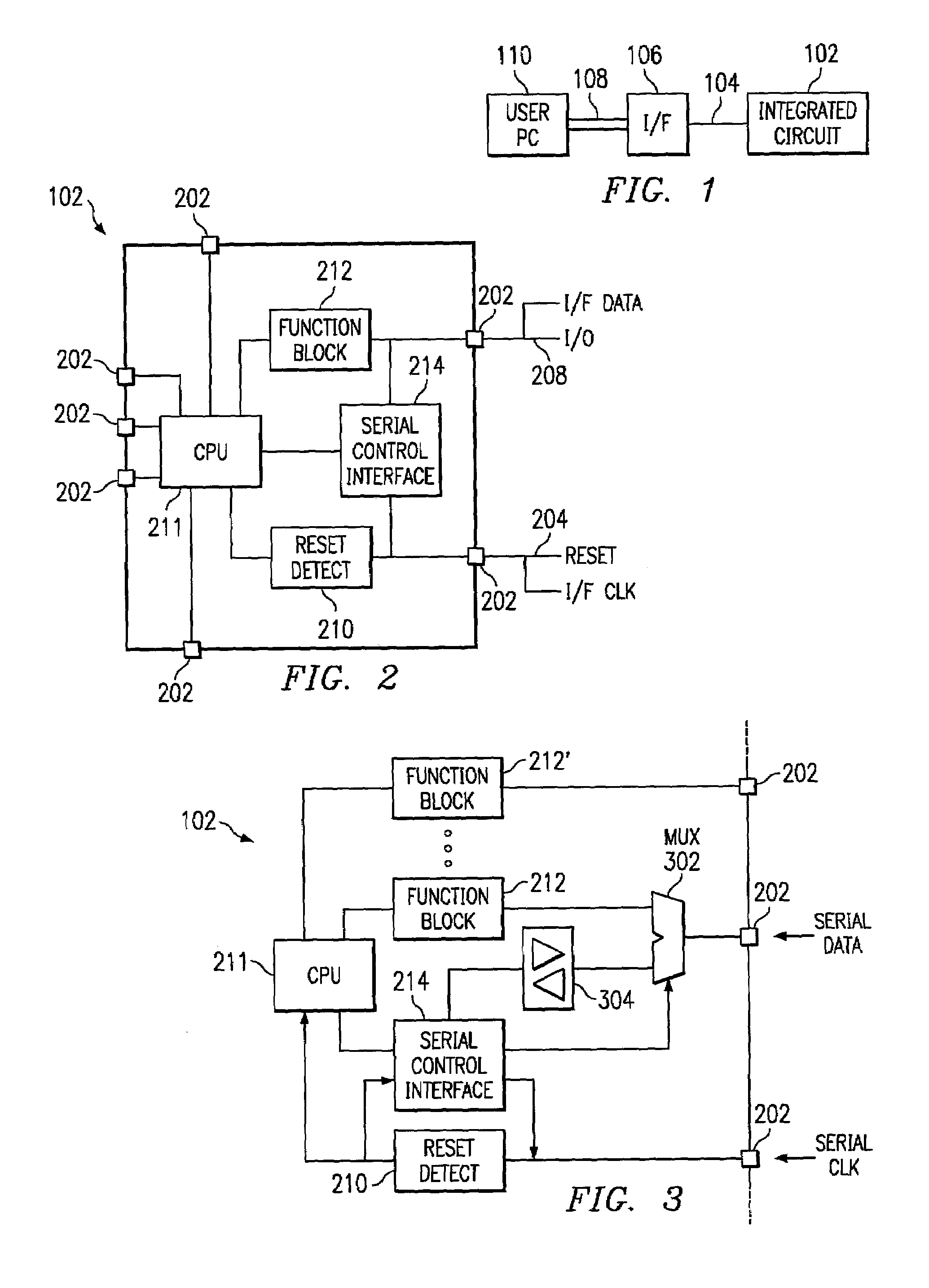
[0027]Referring now to FIG. 1, there is illustrated a diagrammatic view of an integrated circuit 102 having associated therewith interface circuitry for interfacing one or more pins thereof to a serial data bus 104, either one or two wires through a mapping interface block 106—a translator 106. The translator 106 is operable to map a conventional data protocol from a data bus 108 that interfaces with a user PC 110 to the serial data bus 104. The bus 108 can be either a serial data bus such as an RS232 data bus or parallel port. The serial data bus 104 is bi-directional and can be synchronous or asynchronous. In the first disclosed embodiment, this is a synchronous data bus.

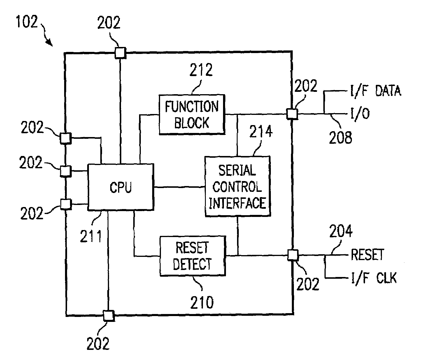
[0028]Referring now to FIG. 2, there is illustrated a diagrammatic view of one embodiment of the present disclosure. The integrated circuit 102 is illustrated as having multiple pins 202 associated therewith, two of which are associated with the serial data interface. In this exemplary disclosure, one of the pins ...


PUM


Abstract

Serial Data Interface. A method of serial communication is provided with an integrated circuit. The operation of the integrated circuit is first interrupted on at least one input/output associated with the operation of the integrated circuit. Serial data is then transmitted over the at least one input/output, the operation of which was interrupted, and during the interruption thereof.

Description

TECHNICAL FIELD OF THE INVENTION[0001]The present invention pertains in general to serial data interfaces and, more particularly, to a serial data interface for mapping data functions and / or timing functions on to a single bi-directional push-pull data bus.BACKGROUND OF THE INVENTION[0002]Due to the limited number of pins that are available on present multi-function integrated circuits, some pins have functions thereof multiplexed to allow different functions to be associated therewith. Some of these can be associated with timing functions, some with data functions and some with status functions. For low pin count devices, one or more pins are typically dedicated to data transfer of multi-bit data words. These data pins typically use some type of serial data protocol, either synchronous or asynchronous. In the synchronous case, there are typically required two pins, one for data and one for clock information. However, there are some synchronous systems that utilize a single wire for...

Claims


Application Information

Patent Timeline
IPC IPC(8): G06F13/42G01R31/317
CPCG06F13/4291G01R31/31712
Inventor FERNALD, KENNETH W.
Owner SILICON LAB INC
Why Eureka
Try Eureka