
Vacuum cleaner with ultraviolet sterilization lamp

a vacuum cleaner and ultraviolet sterilization technology, applied in the field of vacuum cleaners, can solve problems such as the inability to avoid lowering the cleaning efficiency

Inactive Publication Date: 2005-11-29
SAMSUNG GWANGJU ELECTRONICS CO LTD
View PDF19 Cites 16 Cited by
  • Summary
  • Abstract
  • Description
  • Claims
  • Application Information

AI Technical Summary

Benefits of technology

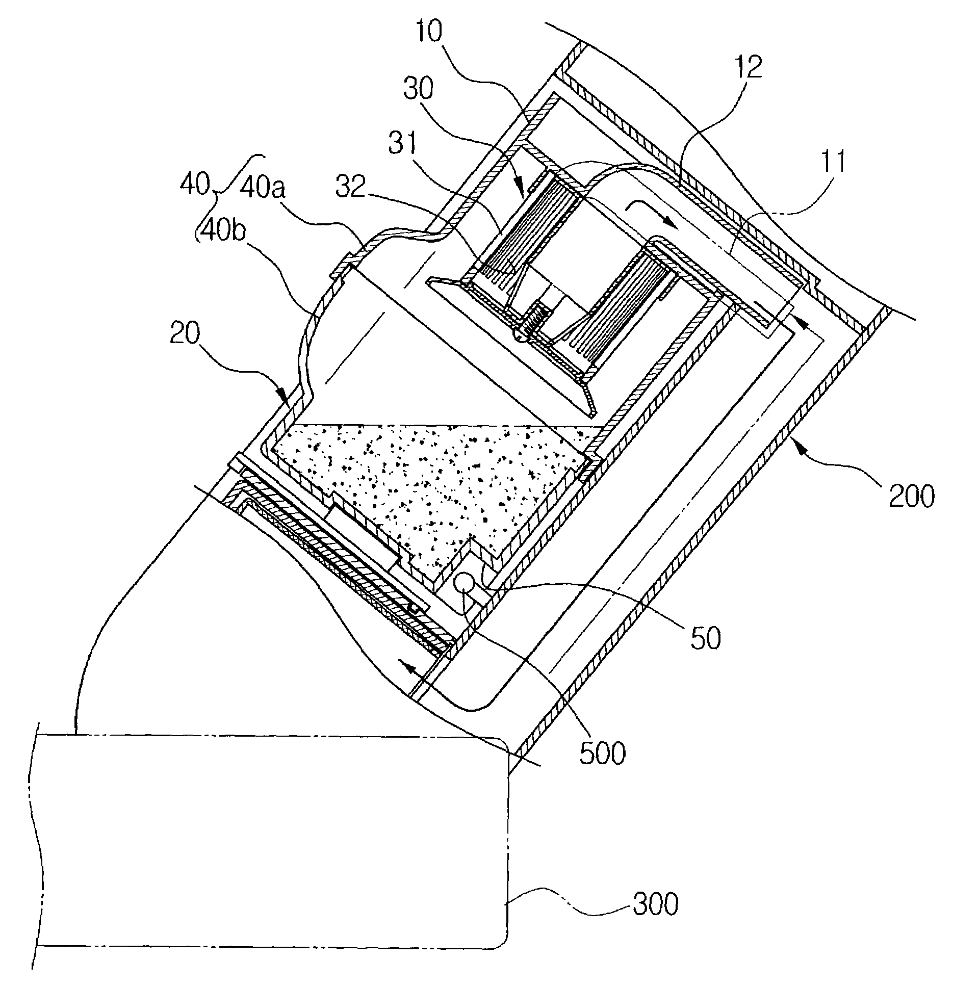
[0014]In order to solve the above described problems, the present invention has been developed to provide a cyclone-type dust collecting apparatus for a vacuum cleaner which can significantly reduce the amount of the dirt reverse flowing through the protruding flow path by expanding the dirt storage unit of the dirt-collecting receptacle, particularly the space between the stored dirt near the protruding flow path and the cyclone body.
[0015]Another object of the present invention is to provide a cyclone-type dust-collecting apparatus for a vacuum cleaner capable of disinfecting the inside of the dirt-collecting receptacle and maintaining the environment outside of the vacuum cleaner clean of bacteria and dust particles.
[0017]The cyclone-type dust-collecting apparatus for a vacuum cleaner according to the present invention for achieving another object has a protruding flow path respectably formed at one side of the cyclone body and the dirt-collecting receptacle for smoothly collecting large particles of dirt separated by centrifugal force from the cyclone stream inside the cyclone body into the dirt-collecting receptacle, wherein the protruding flow path is positioned on the front side when the side of the cleaner body in which the cyclone-type dirt-collecting apparatus is disposed is defined as the back side.
[0019]In addition, since the protruding flow path is formed adjacent the front side of the cyclone-type dust-collecting apparatus, the storage level of the dirt stored near the protruding flow path of the dirt-collecting receptacle is lowered and therefore the space between the dirt near the protruding flow path and the cyclone body is increased and reverse flow of the dirt through the protruding flow path is subsequently reduced.
[0021]The cyclone-type dust-collecting apparatus for a vacuum cleaner of the present invention also may have a partition fixed at the lower end of the cyclone body to be located between the cyclone body and the dirt-collecting receptacle and the partition has a passage hole on which part the protruding flow path is formed. Accordingly, reverse flow of dirt can be effectively prevented as the cyclone body and the dirt-collecting receptacle is divided by the partition.

Problems solved by technology

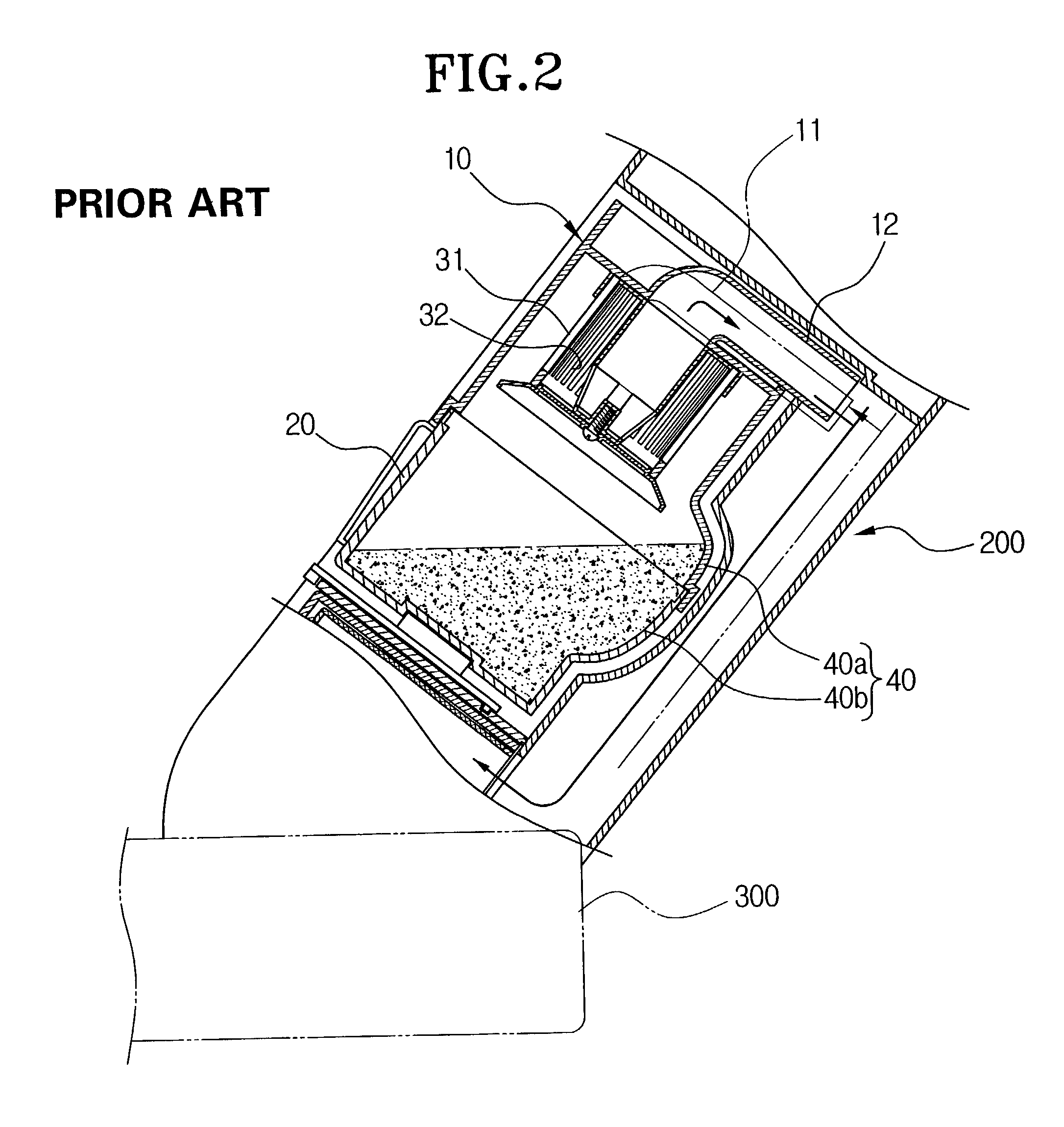
Additionally, large particles of dirt unable to pass through the paths 32 may clog the paths 32, making it impossible to avoid lowering cleaning efficiency.

Method used


Image

  • Vacuum cleaner with ultraviolet sterilization lamp
  • Vacuum cleaner with ultraviolet sterilization lamp
  • Vacuum cleaner with ultraviolet sterilization lamp

Examples


Embodiment Construction

[0030]Hereinafter, a preferred embodiment of the present invention will be described in greater detail with reference to the accompanying drawings.

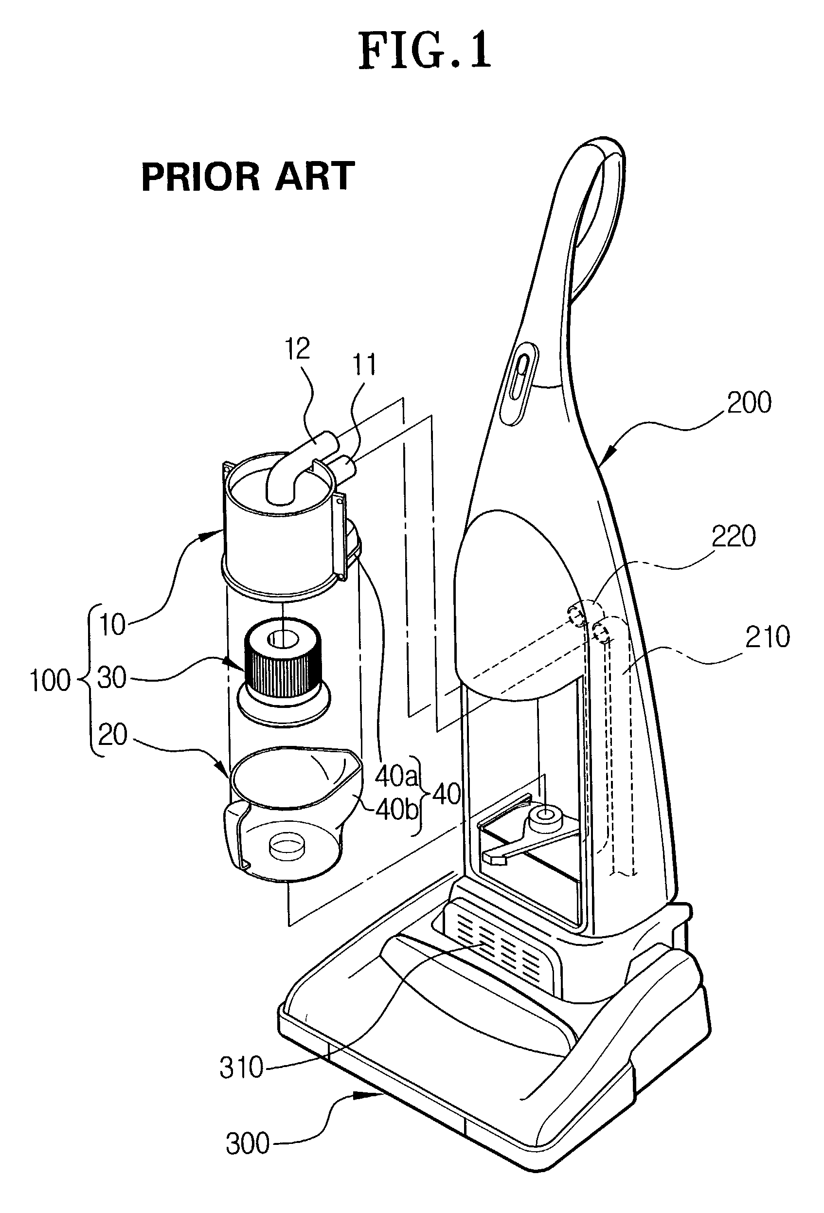
[0031]Referring now to FIGS. 3 and 4, the cyclone-type dust collecting apparatus 100 for a vacuum cleaner according to an embodiment of the present invention comprises a cyclone body 10, a dirt-collecting receptacle 20, a grill assembly 30, a protruding flow path 40, and a lamp-positioning groove 50. As shown in FIG. 4, the vacuum cleaner comprises the cyclone-type dust collecting apparatus 100, a cleaning body 200, a vacuum brush 300, and an ultraviolet lamp 500. For purpose of the drawing figures and the description of the invention, similar elements will be indicated by identical reference numerals to those shown in FIGS. 1 and 2, above.

[0032]The cyclone body 10 has an air inlet pipe 11 and an air discharge pipe 12 and the cleaning body 200, in which the cyclone body is disposed, has an air inlet path 210 connected through with a sucti...


PUM

PropertyMeasurementUnit
centrifugal forceaaaaaaaaaa
angleaaaaaaaaaa
suction forceaaaaaaaaaa

Abstract

The cyclone-type dust collecting apparatus for a vacuum cleaner can reduce reverse flow of dirt and kill any bacteria in the dirt-collecting receptacle. The cyclone-type dust-collecting apparatus has a protruding flow path formed on the front side of the cyclone body and a lamp-positioning groove depressed inwardly at one side of the dirt-collecting receptacle for an ultraviolet lamp disposed in the cleaner body to apply ultraviolet rays radiated into the dirt-collecting receptacle. Accordingly, various bacteria inside the dirt collecting receptacle can be killed as the ultraviolet lamp disposed in the lamp positioning groove of the dirt collecting receptacle continuously applies the ultraviolet rays into the dirt collecting receptacle while the cleaner is on. Moreover, reverse flow of the dirt through the protruding flow path can be reduced as the storage level of the dirt stored near the protruding flow path of the dirt collecting receptacle is lowered and the space between the dirt near the protruding flow path of the dirt collecting receptacle and the cyclone body is expanded.

Description

BACKGROUND OF THE INVENTION[0001]1. Field of the Invention[0002]The present invention relates to a vacuum cleaner, and more particularly, to a cyclone-type dust-collecting apparatus separating dust and dirt from a cyclone stream by a centrifugal force formed by a cyclone stream in the suction air including dust and dirt flown in through the suction port of a vacuum cleaner.[0003]2. Description of the Related Art[0004]A typical example of the above-described cyclone-type dust collecting apparatus for a vacuum cleaner is shown in FIG. 1 and described hereinafter.[0005]In FIG. 1, the reference number 100 is a conventional cyclone-type dust collecting apparatus, 200 is a cleaner body, and 300 is a suction brush. As shown in FIG. 1, the cyclone-type dust collecting apparatus 100 has a cyclone body 10, a dirt-collecting receptacle 20, a grill assembly 30, and a protruding flow path 40.[0006]The cyclone body 10 has an air inlet pipe 11 and an air discharge pipe 12. The air inlet pipe 11 is...

Claims


Application Information

Patent Timeline
Patent Type & Authority Patents(United States)
IPC IPC(8): A47L5/30A47L7/04A47L9/16A61L9/20B01D45/14B04C5/081B04C5/103B04C5/12B04C5/185B04C5/187B04C9/00
CPCA47L7/04A47L9/1608A47L9/1683A61L9/20B01D45/14B04C5/081B04C5/187B04C9/00Y10S55/03A47L9/00A47L9/10A47L9/16
Inventor OH, JANG-KEUNLEE, HYUN-JU
Owner SAMSUNG GWANGJU ELECTRONICS CO LTD
Learn More