

Power tools
a technology of power tools and sockets, applied in the direction of power tools, wrenches, screwdrivers, etc., can solve the problem of small amount of play between the socket and the fastener
- Summary
- Abstract
- Description
- Claims
- Application Information
AI Technical Summary
Benefits of technology
Problems solved by technology
Method used
Image

Examples
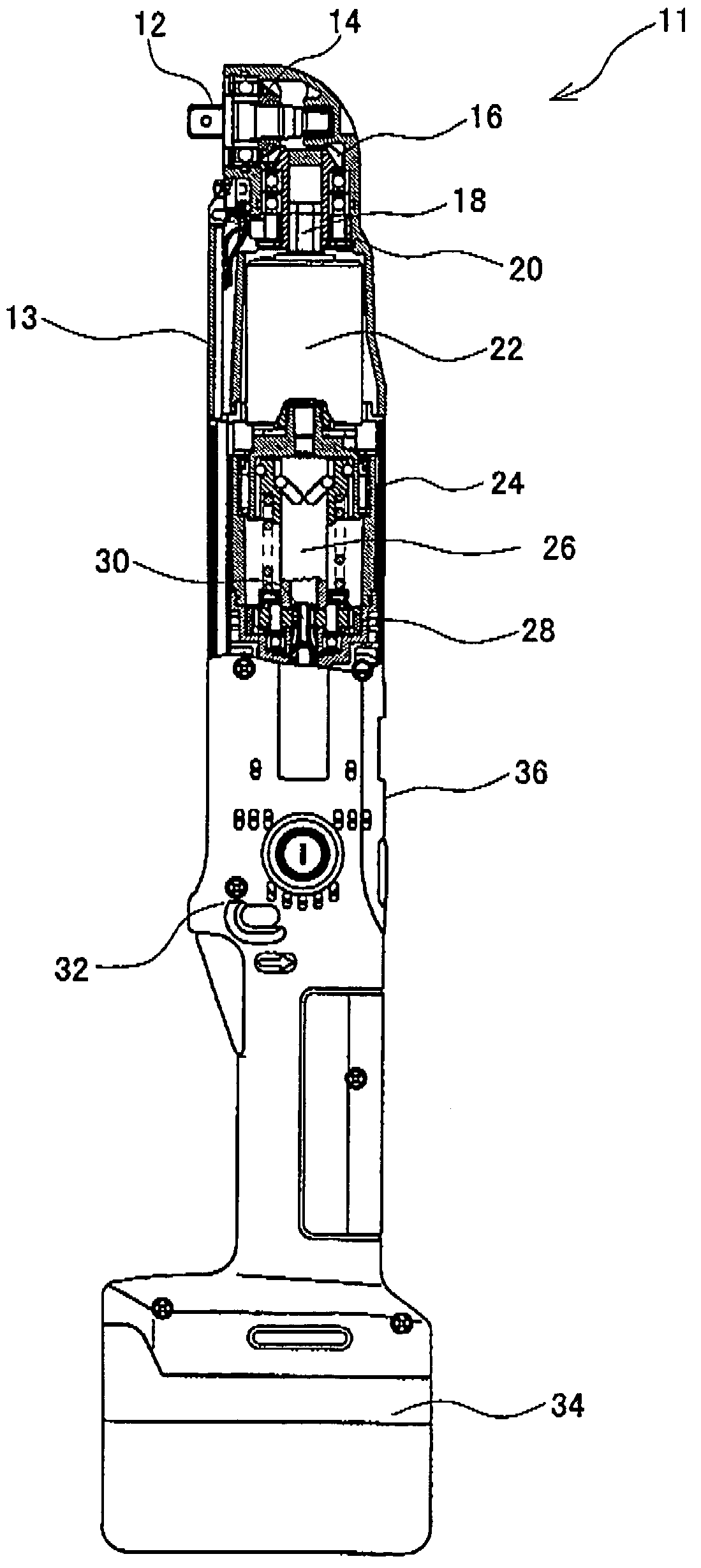
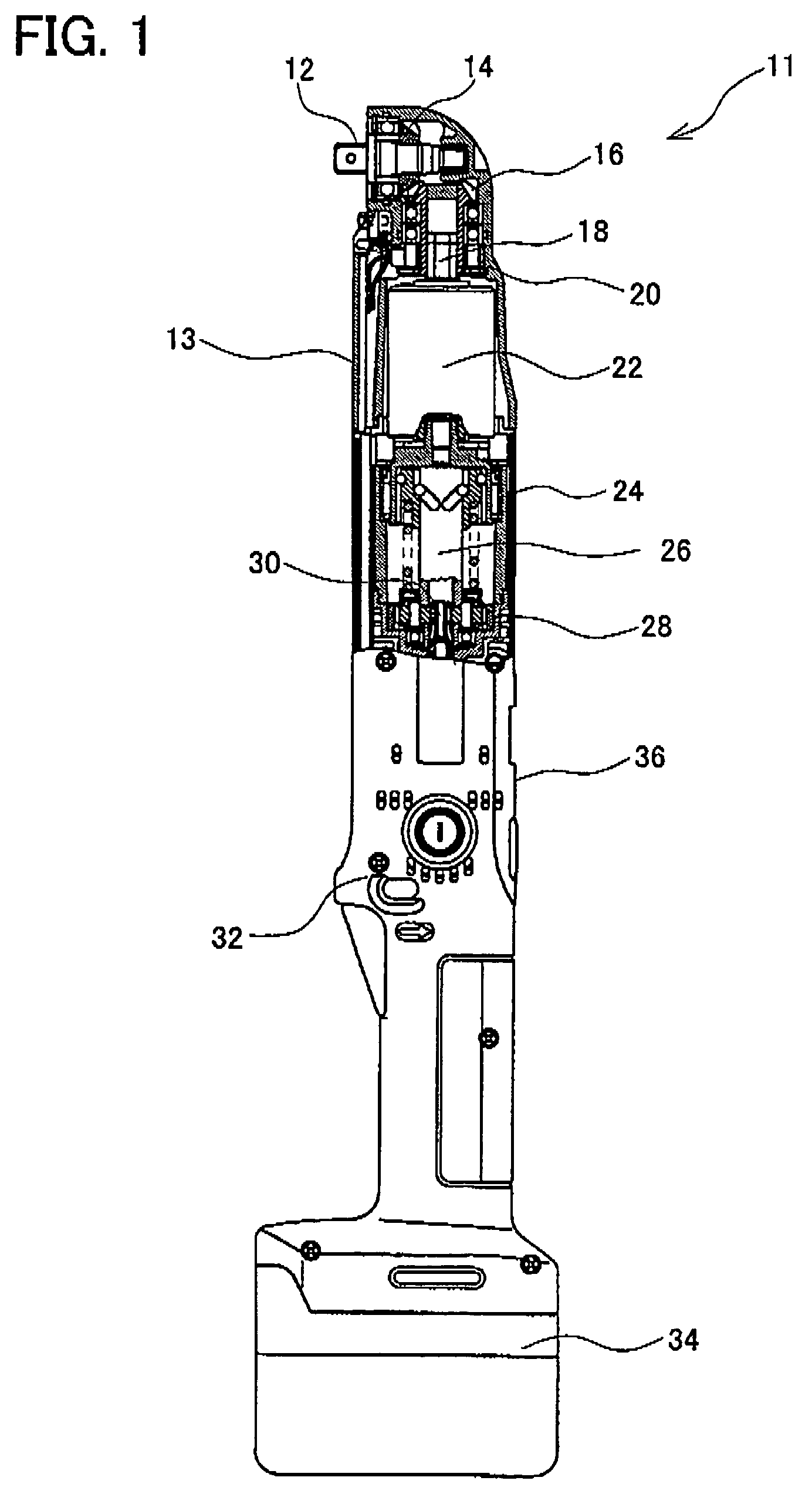
first embodiment
[0088]In the second representative embodiment, microcomputer 60 performs the processes shown in the flowchart of FIG. 9. Further, the first pulse edge detecting process (FIG. 10), the second pulse edge detecting process (FIG. 11), and the third pulse edge detecting process (FIG. 12) are performed in a manner identical to the first representative embodiment However, in the second representative embodiment, the motor stopping process shown at step S36 in FIG. 9 differs from the motor stopping process of the Below, the motor stopping process of the second representative embodiment will be explained with reference to the flowchart of FIG. 14.
[0089]As shown in FIG. 14, in the motor stopping process of the second representative embodiment, microcomputer 60 determines whether a seating detecting flag F has reached ‘1’ (step S92). The seating detecting flag P is a flag for showing whether the fastener is seated, this being ‘1’ when the fastener is seated, and ‘0’ when the fastener is not s...
second embodiment
[0092]In step S104, microcomputer 60 determines whether the seating detecting timer T is equal to 15 milliseconds (step S104). In the case where the seating detecting timer T is not equal to 15 milliseconds (NO in step S104), the process waits until the seating detecting timer T is equal to 15 milliseconds. In the case where the seating detecting timer T is equal to 15 milliseconds (YES in step S104), the process returns to step S12 of FIG. 9, and the process from step S12 is repeated. By this means, in the second embodiment, the process returns to step S12 of FIG. 9 and performs the process from step S12 even after the auto stop timer has started.
[0093]In the case where step S92 is YES (i.e, the seating detecting flag F is ‘1’ and the auto stop timer has started), the value of the variable R (i.e., the changes in the rotational angle of output shaft 18 in the direction of normal rotation during the period from detecting the pulse edge in the first pulse edge detecting process until...
PUM
 Abstract
Description
Claims
Application Information