Closed loop dispensing system

a closed loop and dispensing technology, applied in the direction of liquid flow controllers, liquid transfer devices, packaging, etc., can solve the problems of backflow from the dispensing tube, liquid residue in the bottle may spill therefrom, and backflow may occur, so as to prevent backflow

Inactive Publication Date: 2005-11-29
RD IND INC
View PDF10 Cites 46 Cited by
  • Summary
  • Abstract
  • Description
  • Claims
  • Application Information

AI Technical Summary

Benefits of technology

[0007]This invention relates to a dispensing system for use with a container, such as a bottle or the like, having an outlet opening formed in the upper end thereof. A cap is removably mounted on the container for selectively closing the outlet opening. A dispensing tube extends from the cap for dispensing liquid from the container either through gravity flow or by suction from a mixing machine or the like. A check valve is associated with the cap for preventing backflow from the dispensing tube to the container. The check valve permits liquid flow from the container to the dispensing system in response to suction or gravity. A container insert or throat plug is positioned in the outlet opening of the bottle and includes a valve therein which is open when the cap is mounted on the container, but which is automatically closed when the cap is removed from the container. The cap has a dispensing opening in communication with the valve in the insert for dispensing liquid from the container when the cap is mounted on the container. The insert includes a vent means for relieving pressure or vacuum in the container. A venting membrane covers the vent means. A valve is in communication with the discharge side of the venting membrane for permitting the flow of air into the container, as liquid is drawn therefrom, while preventing the flow of liquid therethrough.
[0008]It is therefore a principal object of the invention to provide an improved dispensing system for corrosive or dangerous liquids contained in a container such as a bottle or the like, when the container is positioned in an inverted condition.
[0010]Still another object of the invention is to provide a dispensing system which is safe and convenient to use.
[0011]Yet another object of the invention is to provide a dispensing system which is reliable in use.

Problems solved by technology

In some prior art devices, when the suction or vacuum is removed from the dispensing tube, backflow may occur.
Further, when the cap is removed from the bottle, backflow from the dispensing tube may also occur.
Additionally, when the cap is removed from the bottle, liquid residue in the bottle may spill therefrom.
Additionally, the conventional prior art systems normally do not prevent the re-use of the bottle which is prohibited in some cases.
Yet another disadvantage of the prior art is that a reliable and efficient venting means for the bottle is not normally provided for relieving vacuum pressure from within the bottle.
While the system of the co-pending application works extremely well when the container is in its normal upright condition, the system may not perfectly function when the container of the co-pending application is inverted.
In such a position, the venting membrane, which would normally permit ambient air to replace the liquid in the container as the liquid is discharged from the container, may become “clogged” due to the liquid coming into contact therewith and crystallizing thereon.
If air is not permitted to enter the container as the liquid is drawn therefrom, a partial vacuum is created in the upper end of the inverted container which will interfere with the discharge of the liquid therefrom.

Method used


Image

  • Closed loop dispensing system
  • Closed loop dispensing system
  • Closed loop dispensing system

Examples


Embodiment Construction

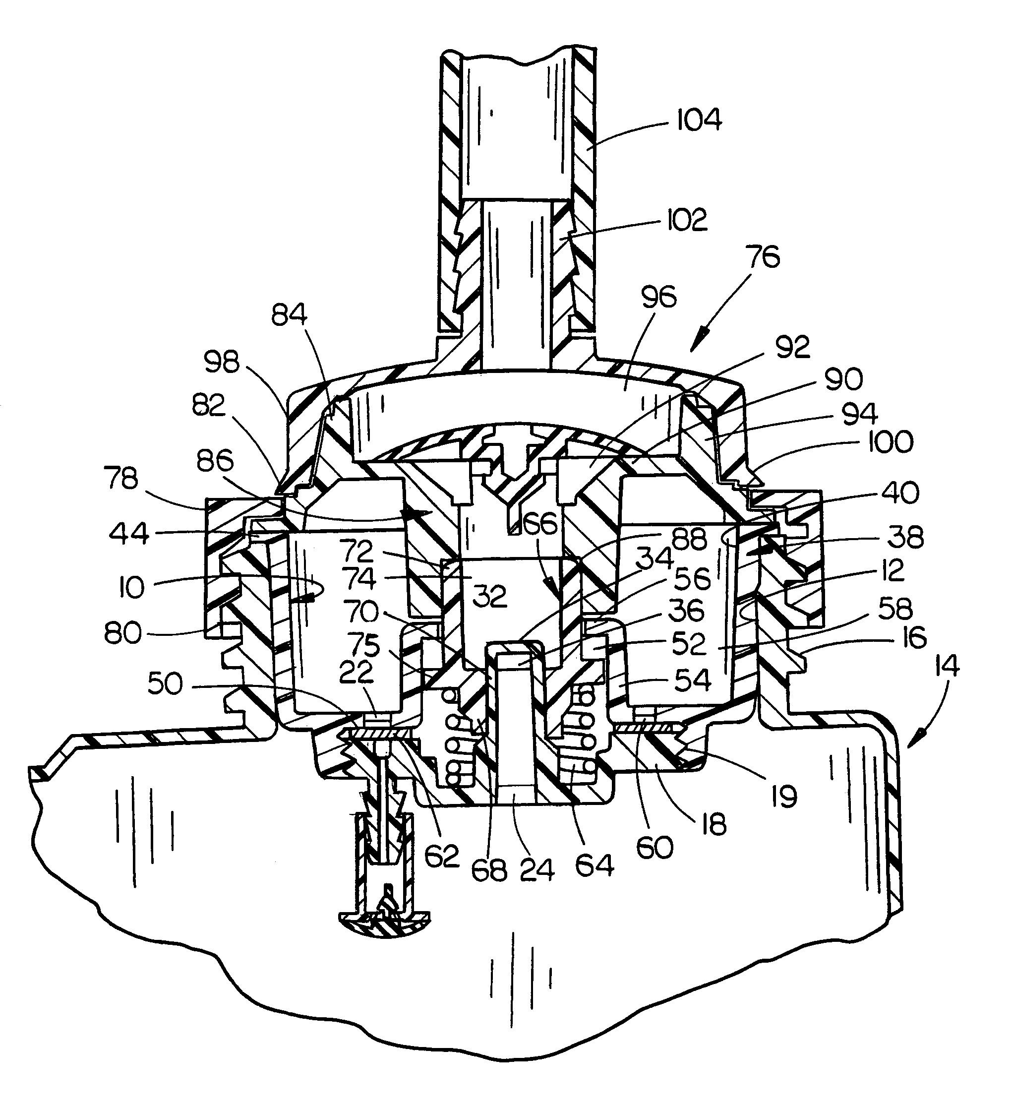
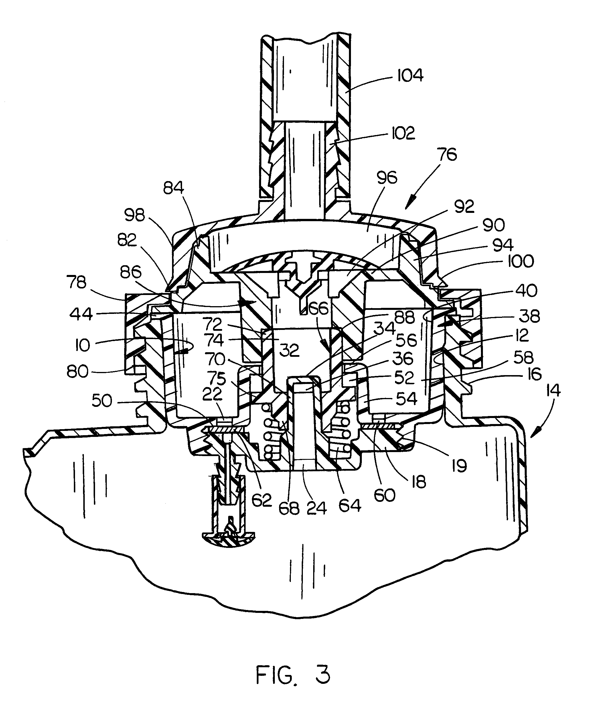
[0020]In the co-pending application, the dispensing thereof is described and shown with the container and the dispensing system being in an upright condition for both shipment and use. In the instant application, the container is shipped and stored in an upright position but is inverted when being used to dispense liquid therefrom. Thus, FIGS. 3 and 6 illustrate the container and dispensing system in an upright position while FIGS. 3a and 6a illustrated the container and dispensing system in an inverted position. The container and the dispensing apparatus will be initially described as being in the upright condition of FIGS. 3 and 6. However, the operation of the system will be described with the container in the inverted position of FIGS. 3a and 6a.

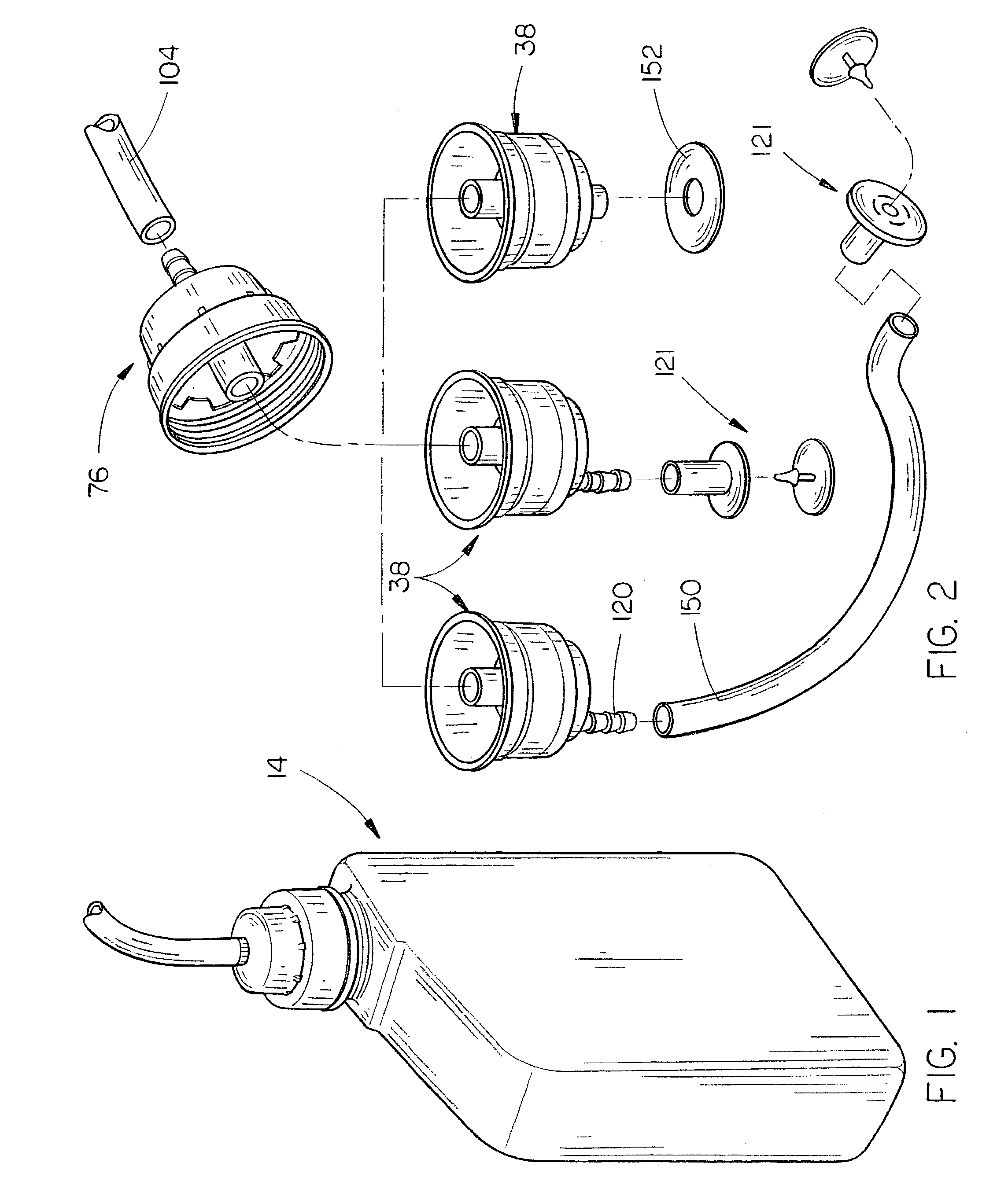
[0021]In FIGS. 1, 3 and 6, a container 14 for dispensing liquid is illustrated in an upright condition. The numeral 10 refers to a throat plug assembly which is press-fitted into the throat or outlet opening 12 of the container 14 which...


PUM


Abstract

A closed loop dispensing system for use on a liquid container such as a bottle or the like for dispensing the liquid contents from the bottle. The outlet opening of the bottle is closed by a throat plug having a valve positioned therein which is open when the container cap is mounted on the container, but which automatically closes when the cap is removed from the container. An inlet opening is provided in the container insert so that liquid may be drawn therethrough. A closure cap is mounted on the bottle and has a dispensing tube extending therefrom for dispensing liquid from the container to a mixing machine or the like. A check valve is associated with the cap for preventing backflow from the dispensing tube to the container and for permitting liquid flow from the container to the dispensing tube in response to suction being applied to the dispensing tube. A precise discharge metering orifice is provided in the valve body as a substitution for proportioners which are normally located downstream of the dispensing system. A valve permits ambient air to enter the interior of the container as liquid is drawn therefrom. The valve prevents the flow of liquid therethrough.

Description

CROSS-REFERENCE TO RELATED APPLICATION[0001]This is a continuation-in-part application of Petitioner's earlier application Ser. No. 10 / 074,469 filed Feb. 12, 2002, now abandoned entitled CLOSED LOOP DISPENSING SYSTEM WITH METERING ORIFICE.BACKGROUND OF THE INVENTION[0002]1. Field of the Invention[0003]This invention relates to a closed loop dispensing system and more particularly to a dispensing system for dispensing corrosive liquid chemicals or dangerous medical liquid products which are typically drawn from the upper end of a container, such as a bottle or the like, to a mixing machine or the like. In the instant invention, the container is inverted with the liquid product being drawn from the lower end thereof by vacuum or by gravity flow.[0004]2. Description of the Related Art[0005]Corrosive liquid chemicals and dangerous medical liquid products are typically contained in a container such as a bottle or the like and are frequently dispensed therefrom to a mixing machine. Normal...

Claims


Application Information

Patent Timeline
Patent Type & Authority Patents(United States)
IPC IPC(8): B67D7/02
CPCB67D7/0294
Inventor LAIBLE, RODNEY
Owner RD IND INC
Why Eureka
Try Eureka