Supercharge Your Innovation With Domain-Expert AI Agents!

Light source substrate

a technology of light source and substrate, which is applied in the direction of lighting support devices, instruments, lighting and heating apparatus, etc., can solve the problems of not meeting the current requirements for lightness and thinness, conventional display devices occupying a certain degree of volume, etc., to improve uniformity and illumination of backlight modules, reduce the quantity of leds, and save time, cost and power

Inactive Publication Date: 2005-11-29
KUO HENG SHENG
View PDF4 Cites 24 Cited by
  • Summary
  • Abstract
  • Description
  • Claims
  • Application Information

AI Technical Summary

Benefits of technology

The solution achieves improved uniformity and luminance in the backlight module while reducing the number of LEDs needed, thereby saving time, cost, and power.

Problems solved by technology

The conventional display device applied for an electron beam shows images on a curved or a flat screen; due to the cathode ray tubes thereof, the conventional display device occupies a certain degree of volume and does not meet current requirements for lightness and thinness.

Method used


Image

  • Light source substrate
  • Light source substrate
  • Light source substrate

Examples


Embodiment Construction

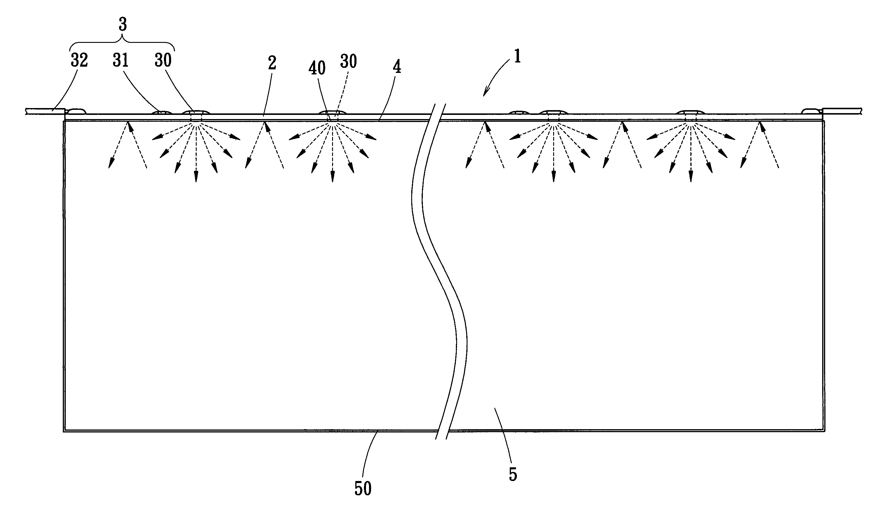
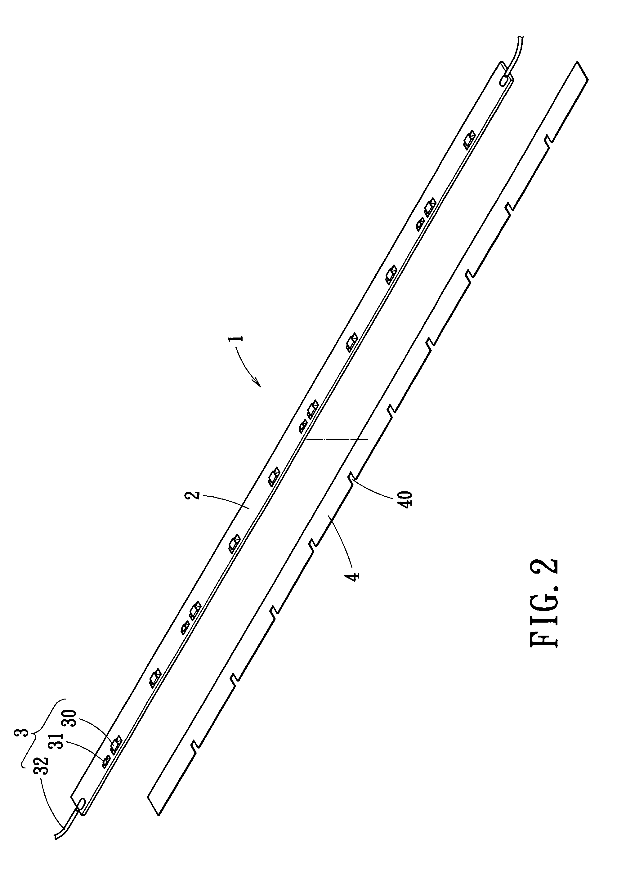
[0019]With respect to FIG. 2 to FIG. 4, the present invention provides a light source substrate 1 adopted for a backlight module including a printed circuit board 2, a lighting assembly 3 disposed on the printed circuit board 2, and a reflection member 4 arranged on a predetermined surface, from which light emits, of the printed circuit board 2, whereby the reflection member 4 reflects the light to the backlight module. The printed circuit board 2 is a dark-colored plate, such as a blackish green plate. The lighting assembly 3 includes a plurality of LEDs 30 and resistors 31 arranged on the printed circuit board 2 in an alternate relationship and two electrical wires 32 respectively electrically connecting two opposing ends of the printed circuit board 2. The reflection member 4 is a white or another light-colored, rectangular shaped sheet to provide good reflection and has a plurality of recesses 40 formed therein and respectively corresponding to the LEDs 30.

[0020]Referring to FIG...


PUM


Abstract

A light source substrate adopted for a backlight module has a printed circuit board, a lighting assembly disposed on the printed circuit board, and a reflection member arranged on a surface, from which light emits, of the printed circuit board, whereby the reflection member reflects the light to the backlight module.

Description

BACKGROUND OF THE INVENTION[0001]1. Field of the Invention[0002]The present invention relates to a light source substrate adopted for a back light module, and particularly relates to a light source substrate with enhanced light intensity.[0003]2. Background of the Invention[0004]As technology develops, modern life closely relates to instruments, computers and appliances, and especially directly relates to those with display devices in a face-to-face manner. The conventional display device applied for an electron beam shows images on a curved or a flat screen; due to the cathode ray tubes thereof, the conventional display device occupies a certain degree of volume and does not meet current requirements for lightness and thinness.[0005]Subsequently, display devices with a backlight module are becoming competitive. As the current liquid crystal display with a thickness one third that of the conventional television saves space, the notebooks have become thinner thinned and lighter for g...

Claims


Application Information

Patent Timeline
Patent Type & Authority Patents(United States)
IPC IPC(8): F21V7/04F21V8/00F21V21/08G01D11/28G02B6/00
CPCG02B6/0031G02B6/0068
Inventor KUO, HENG SHENG
Owner KUO HENG SHENG
Features
  • R&D
  • Intellectual Property
  • Life Sciences
  • Materials
  • Tech Scout
  • Unparalleled Data Quality
  • Higher Quality Content
  • 60% Fewer Hallucinations
Learn More