Intravascular cannulation apparatus and methods of use

a cannulation apparatus and intravascular technology, applied in the field of methods and devices for cannulation, can solve the problems of direct cannulation systems of the prior art, and reducing the field of surgery in the chest cavity

Inactive Publication Date: 2005-11-29
MAQUET CARDIOVASCULAR LLC +1
View PDF36 Cites 53 Cited by
  • Summary
  • Abstract
  • Description
  • Claims
  • Application Information

AI Technical Summary

Benefits of technology

[0059]In one embodiment of the circulatory support method, at least one of the first and second flow paths is advanced using the cut down technique.

Problems solved by technology

Direct cannulation systems of the prior art suffer a variety of drawbacks.
A first drawback is that cannulation can only be performed so long as the chest cavity is maintained open.
Another drawback is that introducing the cannulas and related tubing through the chest cavity reduces the field of surgery, that is, the amount of space within which the surgeon has to operate.
In addition to reducing the field of surgery, the surgeon must make separate incisions for each cannula, with each incision presenting a potential site for leakage and infection.
Direct cannulation through the chest cavity also lengthens the overall time required to perform a CABG procedure because the surgeon must personally position each cannula after opening up the chest cavity.
It is also more costly and ties up valuable hospital resources (i.e. beds, staff, etc .
. . ) for a longer period, which can be especially troubling in emergency room situations where a limited number of beds and staff are commonplace.
While indirect cannulation presents significant improvements over direct cannulation, the prior art indirect cannulation systems are nonetheless flawed.
One disadvantage of prior art indirect cannulation systems is that the cannulas are rigidly fixed to one another and thereby do not provide any degree of adjustability between the distal ends of the cannulas.
This severely restricts the ability to place a particular cannula assembly in the appropriate locations in the circulatory system.
In so doing, it will result in much guess-work in selecting a cannulation assembly of the appropriate size.
Inefficiency in selecting and placing an appropriately sized cannulation assembly translates into increased costs, both in terms of hospital resources (i.e. beds, staff, etc .
. . ) as well as the unnecessary costs associated with discarding cannulation assemblies that were introduced into the circulatory system and later found out to be inappropriately sized for the intended cardiac support function.
Prior art indirect cannulation systems are also limited in terms of their flow characteristics.

Method used


Image

  • Intravascular cannulation apparatus and methods of use
  • Intravascular cannulation apparatus and methods of use
  • Intravascular cannulation apparatus and methods of use

Examples


Embodiment Construction

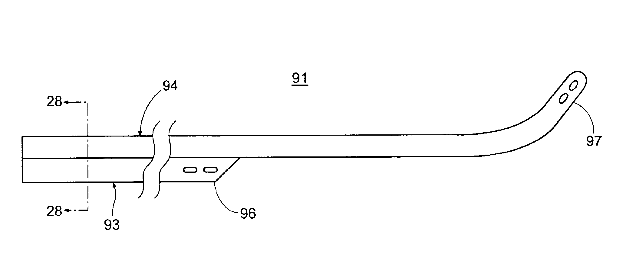
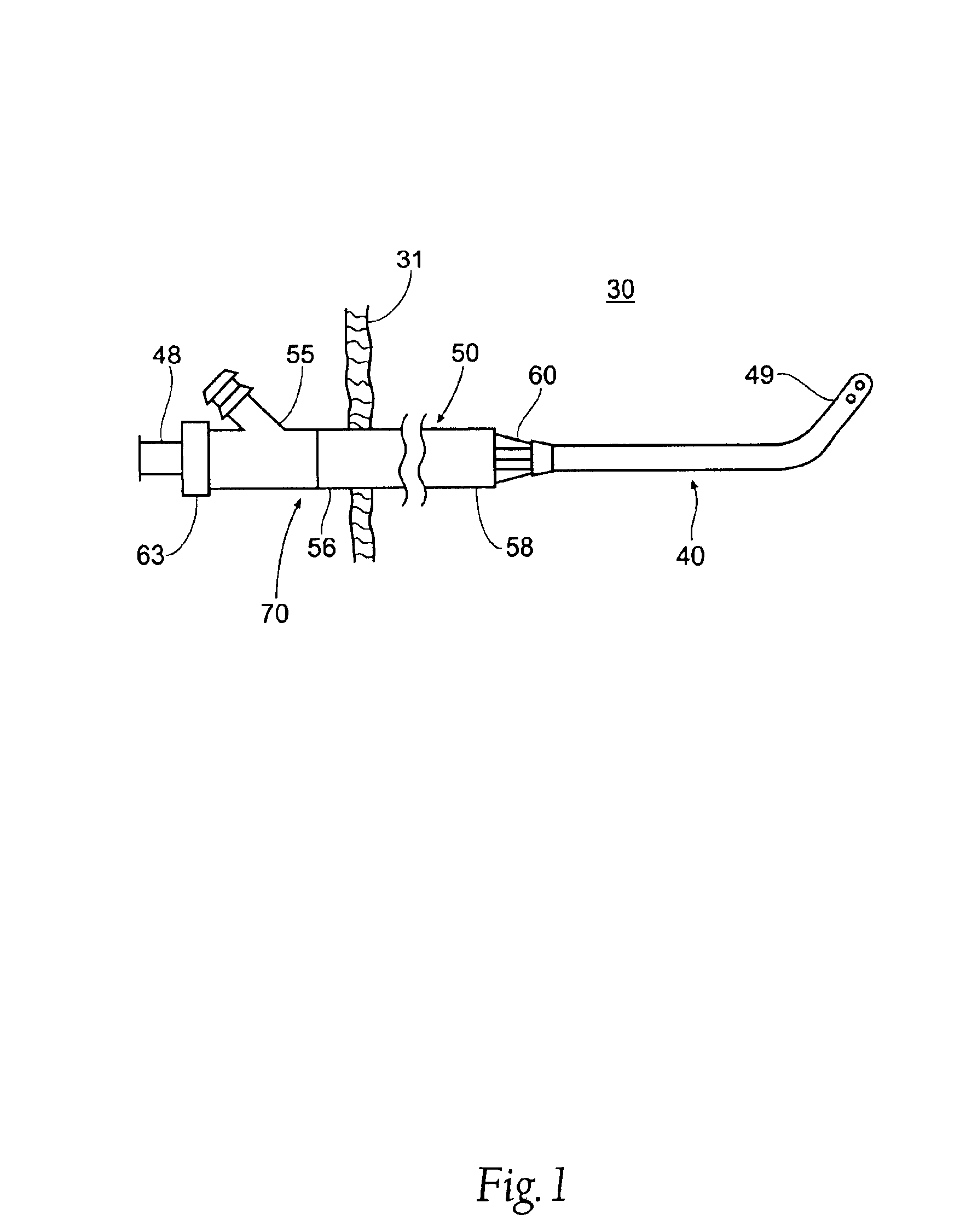
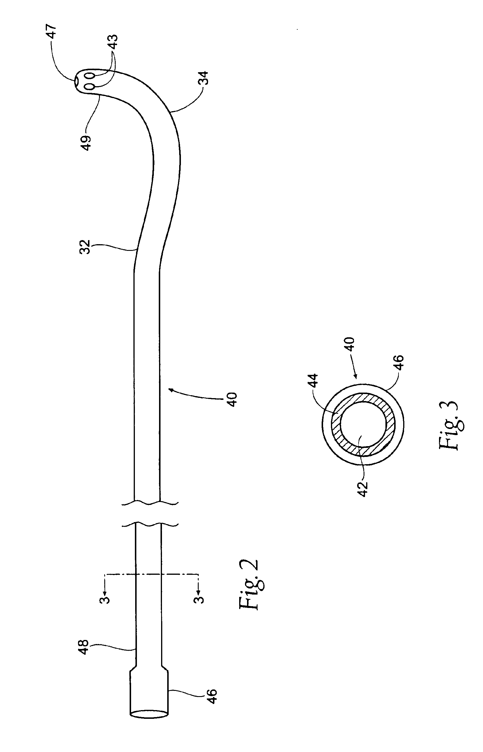
[0125]The present invention involves a cannulation assembly for use in any of a number of broad ranging applications involving the introduction and / or removal of fluids into and / or from the body. The cannulation assembly of the present invention is particularly suited for use in cardiac applications, although it is to be readily understood that the cannulation assembly and methods of the present invention are not to be limited to cardiac applications. By way of example only, the cannulation assembly of the present invention is useful in certain cardiac application, including, but not limited to, procedures involving coronary bypass graft (CABG), cardiopulmonary bypass (CPB), left-heart and / or right-heart assist, open chest and closed chest (minimally invasive), cannulation of a vessel, bridge-to-transplant and / or failure-to-weanfrom-bypass.

[0126]The term “cannula” as used herein is to be defined as a hollow (although not necessarily tubular) instrument designed to be introduced into...


PUM


Abstract

This invention is a cannulation apparatus, and related methods for providing indirect access to a surgical site within a patient. The cannulation apparatus includes at least two fluid flow paths that are slidable coupled (40) (50) to one another, and selectively positional within the patient. The first, the second flow path s may be advanced through a single incision disposed remotely from the surgical field to first, and second predetermined locations within the patient. Exemplary sites for the incision include the groin region or in the neck region of the patient. The cannulation apparatus, and method of the present invention are particularly suited for use in providing cardiopulmonary support during cardiac surgery, including coronary artery bypass graft surgery. The cannulation apparatus of the present invention also provides an entry site for one or more support devices used in the surgical procedure.

Description

CROSS-REFERENCE TO RELATED APPLICATIONS[0001]This application claims the benefit under Title 35, United States Code, §119(e) of U.S. Provisional Application No. 60 / 098,118 filed on Aug. 27, 1998 entitled “Intravascular Cannulation Apparatus and Method of Use.”BACKGROUND OF THE INVENTION[0002]1. Field of the Invention[0003]The present invention relates generally to methods and devices for cannulation and, more particularly, to an intravascular cannulation assembly having at least two flow paths slidably coupled to one another suitable for use in a variety of cardiac procedures.[0004]2. Description of Related Art[0005]Cannulas and cannulation techniques are used in medical applications for transporting fluid into or out of the body. An area of proliferated use is cardiac surgery, where cannulation is routinely employed to transport fluid into, out of, or between various points in the circulatory system. This may be done for the purpose of performing cardiac procedures including, but n...

Claims


Application Information

Patent Timeline
Patent Type & Authority Patents(United States)
IPC IPC(8): A61M1/36A61M25/00A61M31/00A61M37/00
CPCA61M25/0043A61M25/0068A61M1/3659A61M1/3666A61M25/0069A61M25/007A61M25/0074A61M25/008A61M25/0082A61M2025/0031A61M2025/0034A61M2025/0037A61M2025/0039
Inventor ABOUL-HOSN, WALID NKANZ, WILLIAM R
Owner MAQUET CARDIOVASCULAR LLC
Why Eureka
Try Eureka