Airfoil qualification system and method

a technology of airfoil blades and qualification systems, applied in the field of automatic airfoil blade qualification systems and methods, can solve the problems of complex peening machine design, time-consuming and laborious process, and high overall manufacturing cost of compressor blades

Inactive Publication Date: 2005-11-29
GENERAL ELECTRIC CO
View PDF44 Cites 43 Cited by
  • Summary
  • Abstract
  • Description
  • Claims
  • Application Information

AI Technical Summary

Benefits of technology

[0010]In another embodiment, an airfoil qualification system for measuring and reworking an airfoil includes a measurement and reworking station including a measuring system configured to obtain spatial position data relative to a fixed reference frame for each of a plurality of points on the surface and further including a treatment system for directing altering treatments to the airfoil, a data processing system in communication with the measuring and reworking station, the data processing system including, a mapping module programmed to use the spatial position data to form a three dimensional map of the surface, a deviation determination module programmed to determine a point deviation for each of at least a portion of the plurality of surface points, a required treatment determination module for calculating necessary treatments for bring the airfoil in conformance with a target model, and a treatment control module for providing instructions to the treatment system in the measurement and reworking station.

Problems solved by technology

The qualification process is time-consuming and requires highly skilled labor.
The process adds significantly to the overall manufacturing cost of compressor blades.
A highly tapered material may require several shot sizes although this complicates peening machine design.
The diffuse nature of the flame makes the process difficult and success relies heavily on operator skill, especially to establish a steep temperature gradient in thin sections and materials with a high thermal conductivity.

Method used


Image

  • Airfoil qualification system and method
  • Airfoil qualification system and method
  • Airfoil qualification system and method

Examples


Embodiment Construction

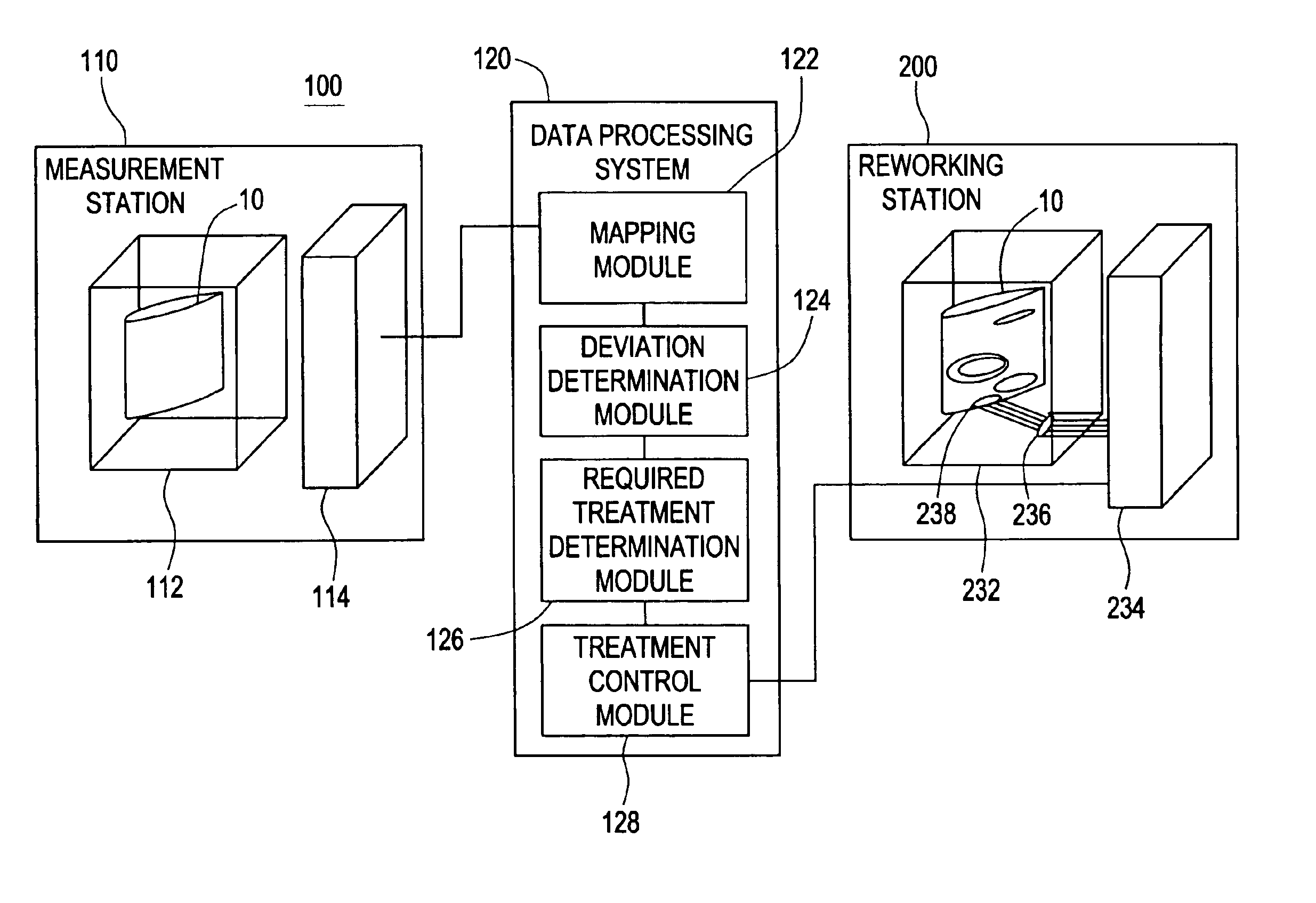
[0021]An automated airfoil blade qualification method is presented which combines automated measurement technologies with technologies to form parts without the use of dies. The dieless technologies preferably include laser forming, laser shock peening and shot-peen processes, each of which affects part geometry by a surface treatment process. Laser forming operates via temperature gradients and thermal stresses induced by a scanning laser beam. Laser shock peening operates by focusing an intense beam on an area covered with an ablative material, which, when hit, sends intense shock waves into the part. Shot peening is a process that bombards the surface with many small spherical hard particles. All processes result in localized plastic deformation and residual stresses, which then alter the equilibrium shape of the workpiece.

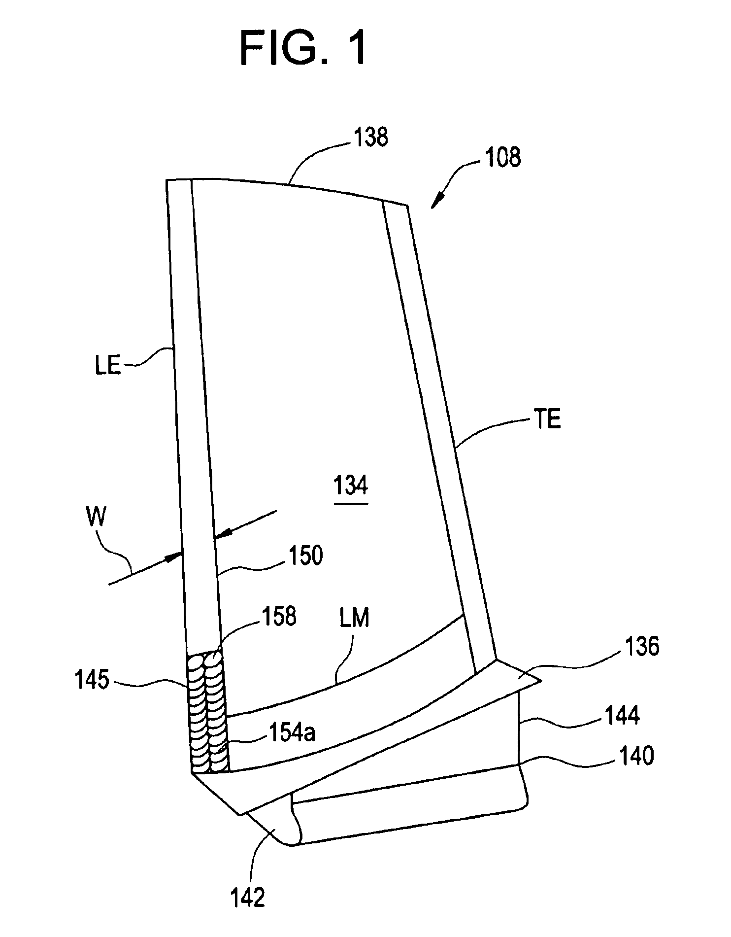
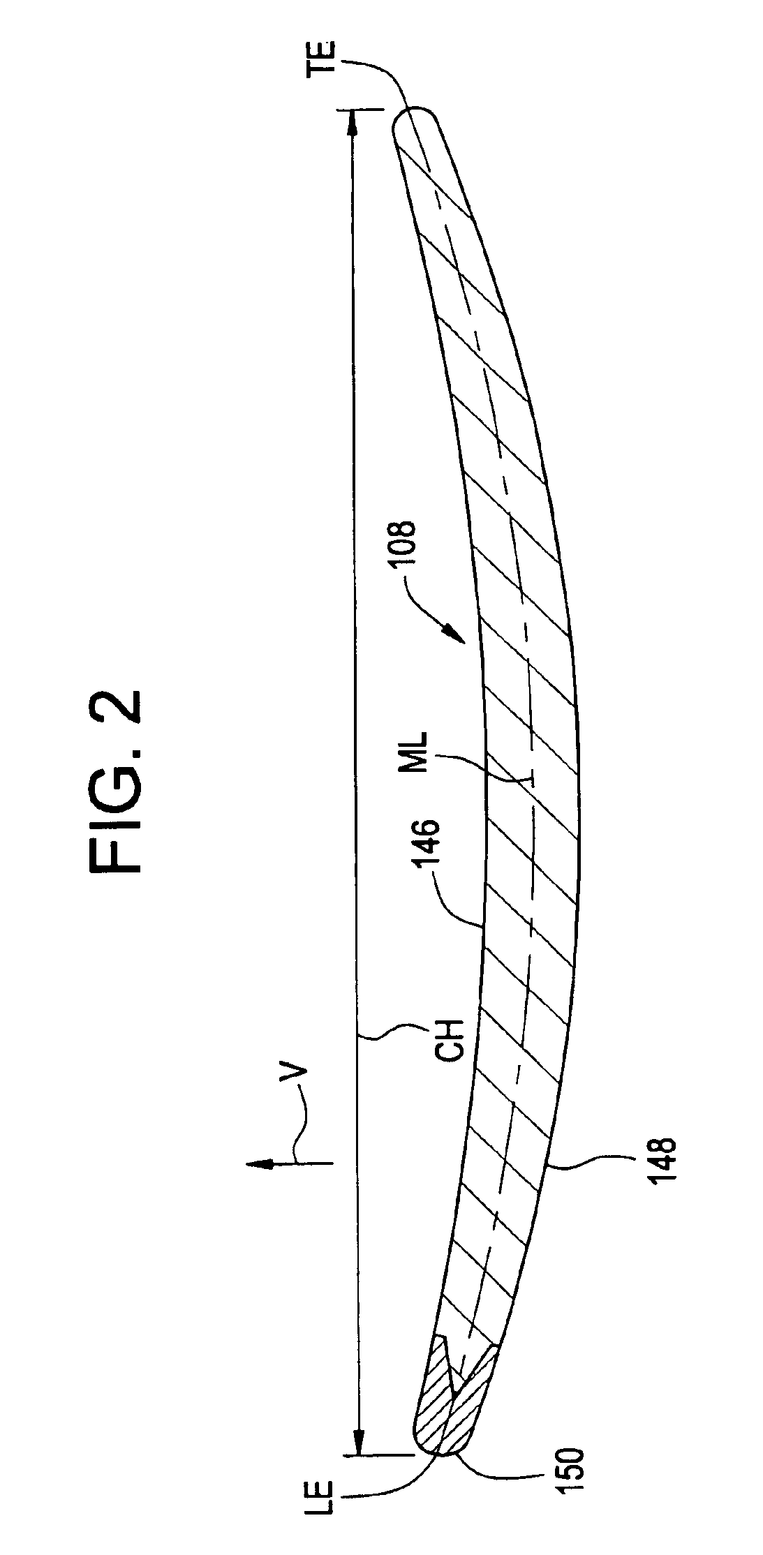
[0022]An exemplary embodiment of laser shock peening is shown in FIGS. 1-3. Referring to FIGS. 1-2, an exemplary airfoil blade 108 includes an airfoil 134 exte...


PUM

PropertyMeasurementUnit
processingaaaaaaaaaa
timeaaaaaaaaaa
fatigue strengthaaaaaaaaaa

Abstract

A method for qualifying airfoil blades includes securing an airfoil blade into a fixture, taking digital measurements of the airfoil blade, comparing the digital measurements of the airfoil blade with measurements of a target model, calculating deviations between the digital measurements of the airfoil blade and the measurements of the target model, determining a required treatment for the airfoil blade to conform with the measurements of the target model, directing a reworking system to provide the required treatment to the airfoil blade, and repeating the previous steps until it is determined that no further treatment is required. An airfoil qualification system for performing the method for qualifying airfoil blades includes a measurement station, a data processing system in communication with the measurement station and for determining a point deviation from a surface standard point for each of at least a portion of the plurality of surface points and for determining a required treatment of the airfoil, and a reworking station for directing treatments to the airfoil in response to input from the data processing system.

Description

STATEMENT REGARDING FEDERALLY SPONSORED RESEARCH AND DEVELOPMENT[0001]The U.S. Government may have certain rights in this invention pursuant to contract number 70NANB2H3031 awarded by the National Institute of Standards and Technology, Advanced Technology Program.BACKGROUND OF THE INVENTION[0002]This invention relates generally to airfoil blades, and, more particularly, this invention relates to an automated airfoil blade qualification system and method.[0003]Aircraft engine compressor blades are manufactured to stringent airfoil tolerances, and all blades must pass a qualification process in which dimensions are checked and, if necessary, are manually brought into compliance. Dimensions of primary interest are section contours, twist, and bow. The qualification process is time-consuming and requires highly skilled labor. In many instances, blades are still deformed by hand. The process adds significantly to the overall manufacturing cost of compressor blades.[0004]Shot peening is u...

Claims


Application Information

Patent Timeline
Patent Type & Authority Patents(United States)
IPC IPC(8): B23P6/00F01D25/00F01D5/00F01D21/00F04D29/38G06T7/00
CPCB23P6/002F01D5/005F01D21/003G06T7/001G06T2200/04G06T2207/30164F05D2230/80
Inventor MIKA, DAVID P.KARAFILLIS, APOSTOLOS P.
Owner GENERAL ELECTRIC CO
Why Eureka
Try Eureka