

Battery fuel gauge using safety circuit
a safety circuit and battery technology, applied in the direction of alarms, instruments, transportation and packaging, etc., can solve the problems of battery dead, accumulation of errors, and how much “charge” is left in the battery
- Summary
- Abstract
- Description
- Claims
- Application Information
AI Technical Summary
Benefits of technology
Problems solved by technology
Method used
Image

Examples
Embodiment Construction
[0014]A preferred embodiment of the invention is now described in detail. Referring to the drawings, like numbers indicate like parts throughout the views. As used in the description herein and throughout the claims, the following terms take the meanings explicitly associated herein, unless the context clearly dictates otherwise: the meaning of “a,”“an,” and “the” includes plural reference, the meaning of “in” includes “in” and “on.”
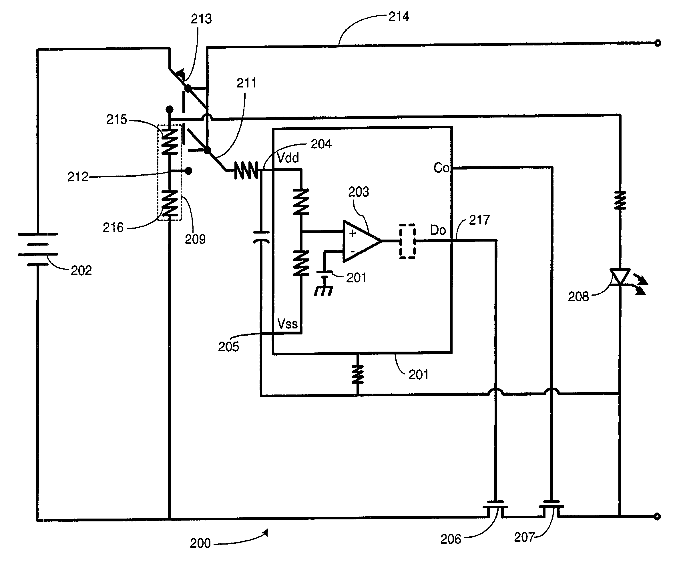
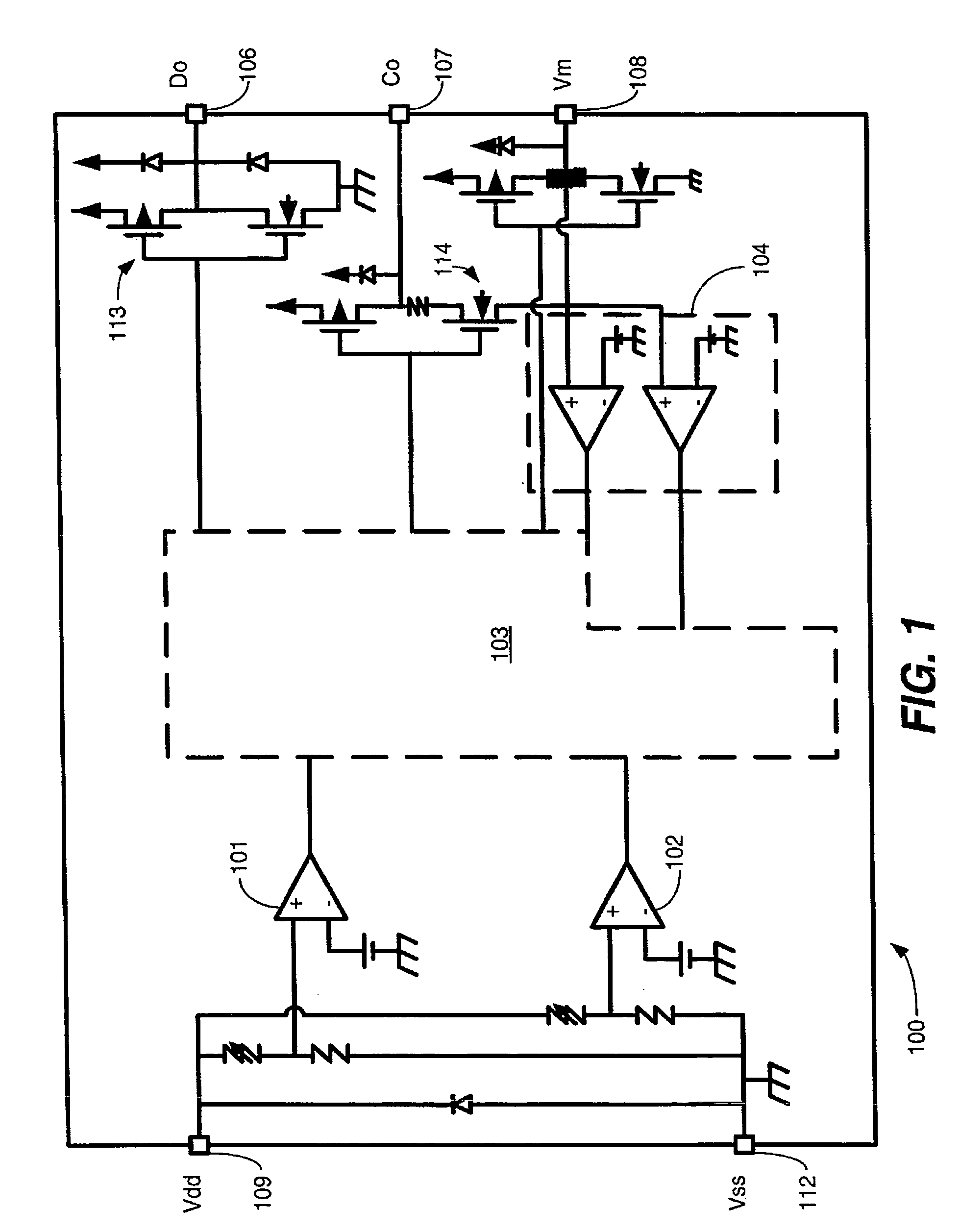
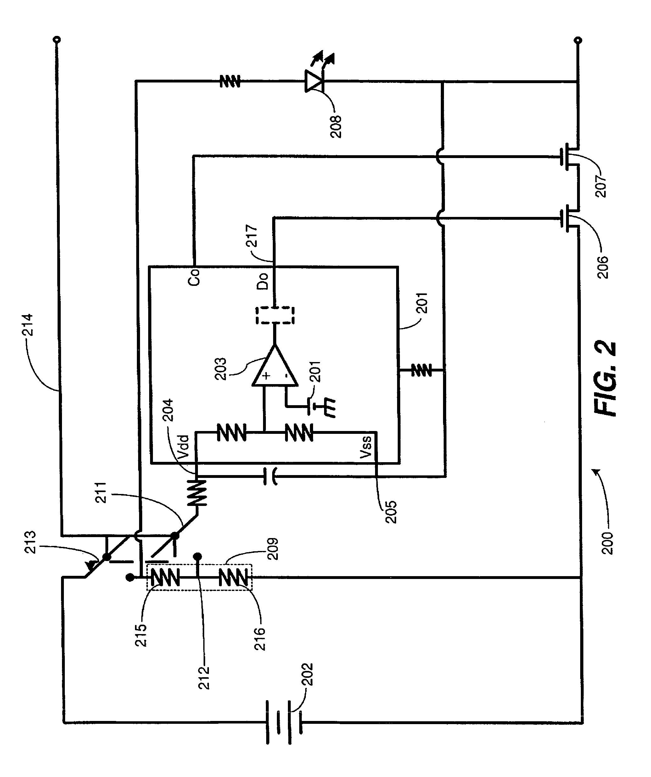
[0015]This invention is a simple, inexpensive fuel gauge circuit that gives a user an approximation of the amount of energy stored in a rechargeable cell. The fuel gauge circuit employs a battery protection circuit and takes advantage of the safety circuit's internal undervoltage detector circuit to determine the cell capacity. By coupling a scaled cell voltage to the undervoltage detector of the safety circuit, the invention can determine whether the cell voltage—which is proportional to energy capacity—is above or below a predetermined threshold.
[0016]...
PUM
 Abstract
Description
Claims
Application Information