Imaging lens

a technology of imaging lens and lens body, which is applied in the field of imaging lens, can solve the problems of not meeting the requirements of specification, unable to obtain sufficient design versatility, and unable to increase the angle of view,

Inactive Publication Date: 2005-11-29
SEIKO EPSON CORP
View PDF13 Cites 51 Cited by
  • Summary
  • Abstract
  • Description
  • Claims
  • Application Information

AI Technical Summary

Problems solved by technology

Meanwhile, since the recording density of an imaging element used in a portable terminal and the like has been rapidly increased recently, the situation has come where a lens system formed of one or two lenses that were used in an imaging element initial stage can not obtain sufficient versatility of design and can not satisfy a required specification.
Therefore, increasing an angle of view is difficult, so that the angle of view in the embodiment also remains at about 20 degrees, which is small.
In addition, since effective correction of chromatic aberration is difficult, the widening of the angle of view is limited.
However, the versatility of designing thereof is insufficient to respond to a further increase in resolution of an imaging element.

Method used


Image

  • Imaging lens
  • Imaging lens
  • Imaging lens

Examples


examples

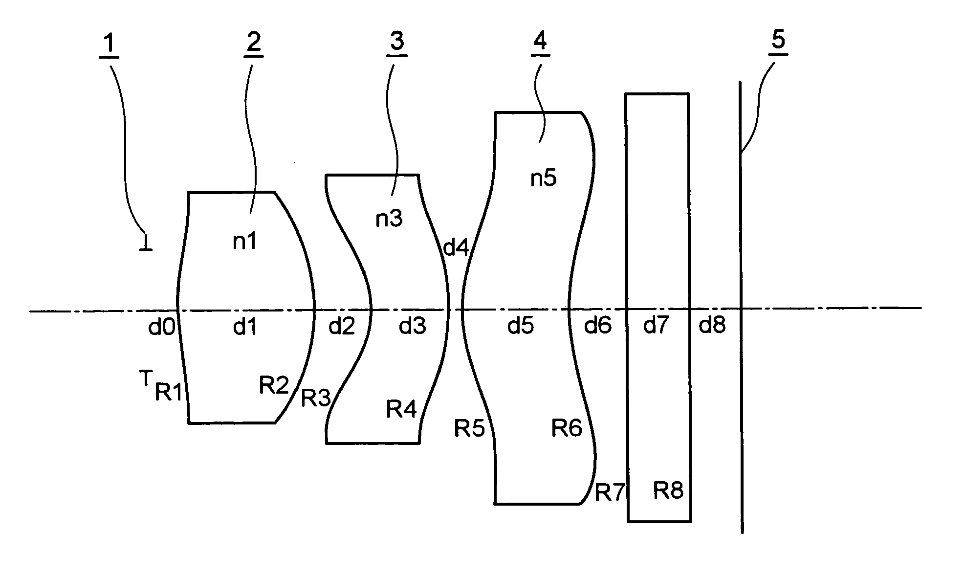
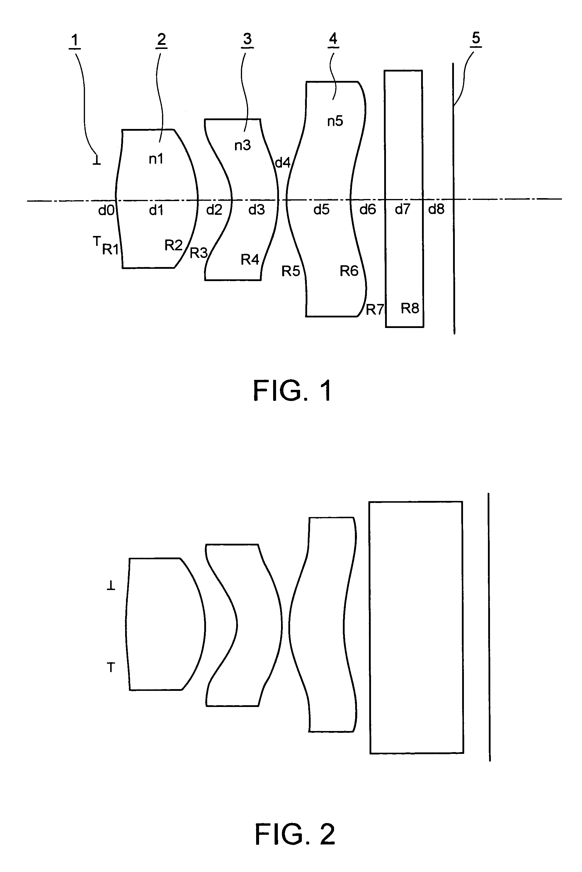
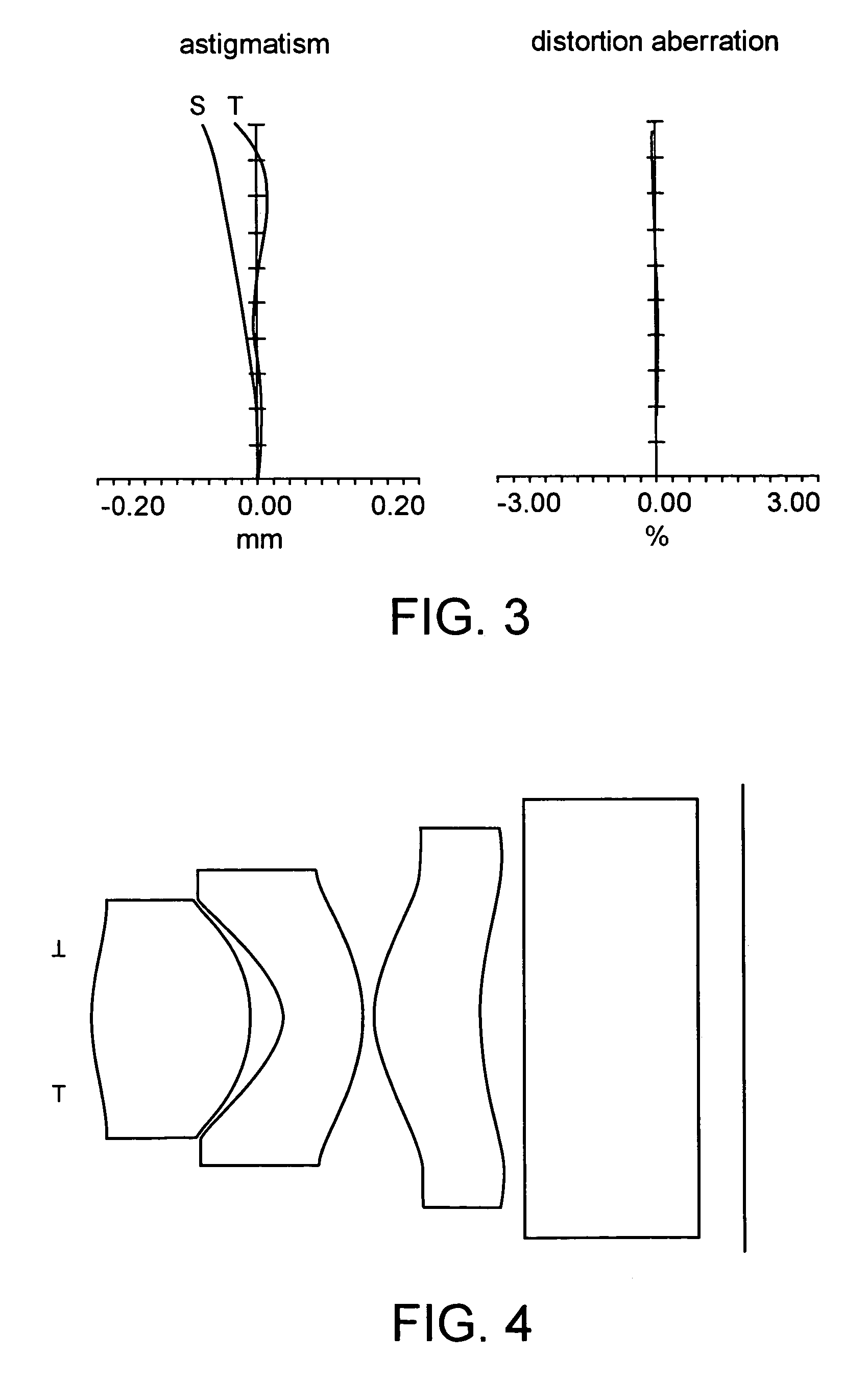
[0060]Next, examples of the present invention will be explained referring to specific number examples.

[0061]

TABLE 1radius ofcurvaturedistancerefractive indexdispersionexample 1d00.2451R12.769d11.261n11.533ν155.32R2−1.702d20.528n2ν23R3−0.764d30.700n31.935ν320.94R4−1.699d40.100n4ν45R51.177d50.990n51.533ν555.36R61.944d60.5267R70.000d70.550glass8R80.000d80.500example 2d00.2451R13.452d11.274n11.533ν155.32R2−1.426d20.504n2ν23R3−0.683d30.700n31.935ν320.94R4−1.622d40.100n4ν45R51.182d50.897n51.533ν555.36R62.813d60.3817R70.000d71.500quartz8R80.000d80.400example 3d00.2721R12.234d11.355n11.494ν157.42R2−1.601d20.334n2ν23R3−0.591d30.700n31.591ν329.94R4−1.500d40.100n4ν45R51.191d50.998n51.494ν557.46R62.217d60.5927R70.000d70.550glass8R80.000d80.500example 4d00.2791R12.531d11.412n11.494ν157.42R2−1.210d20.269n2ν23R3−0.513d30.700n31.591ν329.94R4−1.791d40.100n4ν45R51.041d50.943n51.494ν557.46R63.482d60.3977R70.000d71.500quartz8R80.000d80.400example 5d00.1621R13.783d11.438n11.560ν167.32R2−2.512d20.864n2ν2...


PUM


Abstract

A bright, small, and inexpensive imaging lens system is provided with a short total length that can provide more than a 30 degree viewing angle and whose aberrations are excellently corrected. The imaging lens includes, in order from an object side, a positive first lens with a convex surface facing the object side, an aperture stop provided on the object side or an image side of the first lens, a meniscus second lens with a concave surface facing the object side, and a meniscus third lens with a convex surface facing the object side. Furthermore, at least one of the first lens and the second lens includes an aspheric surface, and the third lens is a biaspheric lens. In addition, the second lens and the third lens have paraxial focal lengths whose signs are different. When v max and v min are the maximum Abbe number and the minimum Abbe number among the lenses, respectively, the condition, 1.25<v max / v min, is satisfied.

Description

RELATED APPLICATIONS[0001]Japanese Patent Application No. 2003-011239 filed on Jan. 20, 2003 is hereby incorporated by reference in its entirety.BACKGROUND OF THE INVENTION[0002]1. Technical Field of the Invention[0003]The present invention relates to an imaging lens that forms an image of an object on an image receiving surface.[0004]2. Description of the Related Art[0005]Recently, a photographic camera module has come to be provided to portable terminals such as cellular phones. This type of equipment needs miniaturizing of the whole camera module including an optical system, an imaging element, and an image processing device in order to enhance the portability thereof. Regarding imaging elements such as a CCD and a CMOS, a high resolution and small imaging element with miniaturized pixel size has been rapidly spreading. As an optical system responding to such an imaging element, an optical system that satisfies all needs such as small size, low price, high resolution and excellen...

Claims


Application Information

Patent Timeline
Patent Type & Authority Patents(United States)
IPC IPC(8): G02B9/16G02B13/00G02B13/18
CPCG02B9/16G02B13/003G02B13/0035
Inventor MATSUO, EIKI
Owner SEIKO EPSON CORP
Why Eureka
Try Eureka