Real-time dynamic image reconstruction

a real-time dynamic, image reconstruction technology, applied in tomography, ultrasonic/sonic/infrasonic diagnostics, instruments, etc., can solve problems such as disadvantages in lag, and achieve the effect of rapid image reconstruction

Inactive Publication Date: 2005-11-29
MARCONI MEDICAL SYST ISRAEL
View PDF36 Cites 37 Cited by
  • Summary
  • Abstract
  • Description
  • Claims
  • Application Information

AI Technical Summary

Benefits of technology

[0010]It is an object of the present invention to provide a method for rapid image reconstruction based on axial or helical-scan CT data.

Problems solved by technology

The lag is particularly disadvantageous when CT imaging is used to track the progress of a physiological process, such as the flow of a contrast material.

Method used


Image

  • Real-time dynamic image reconstruction
  • Real-time dynamic image reconstruction
  • Real-time dynamic image reconstruction

Examples


Embodiment Construction

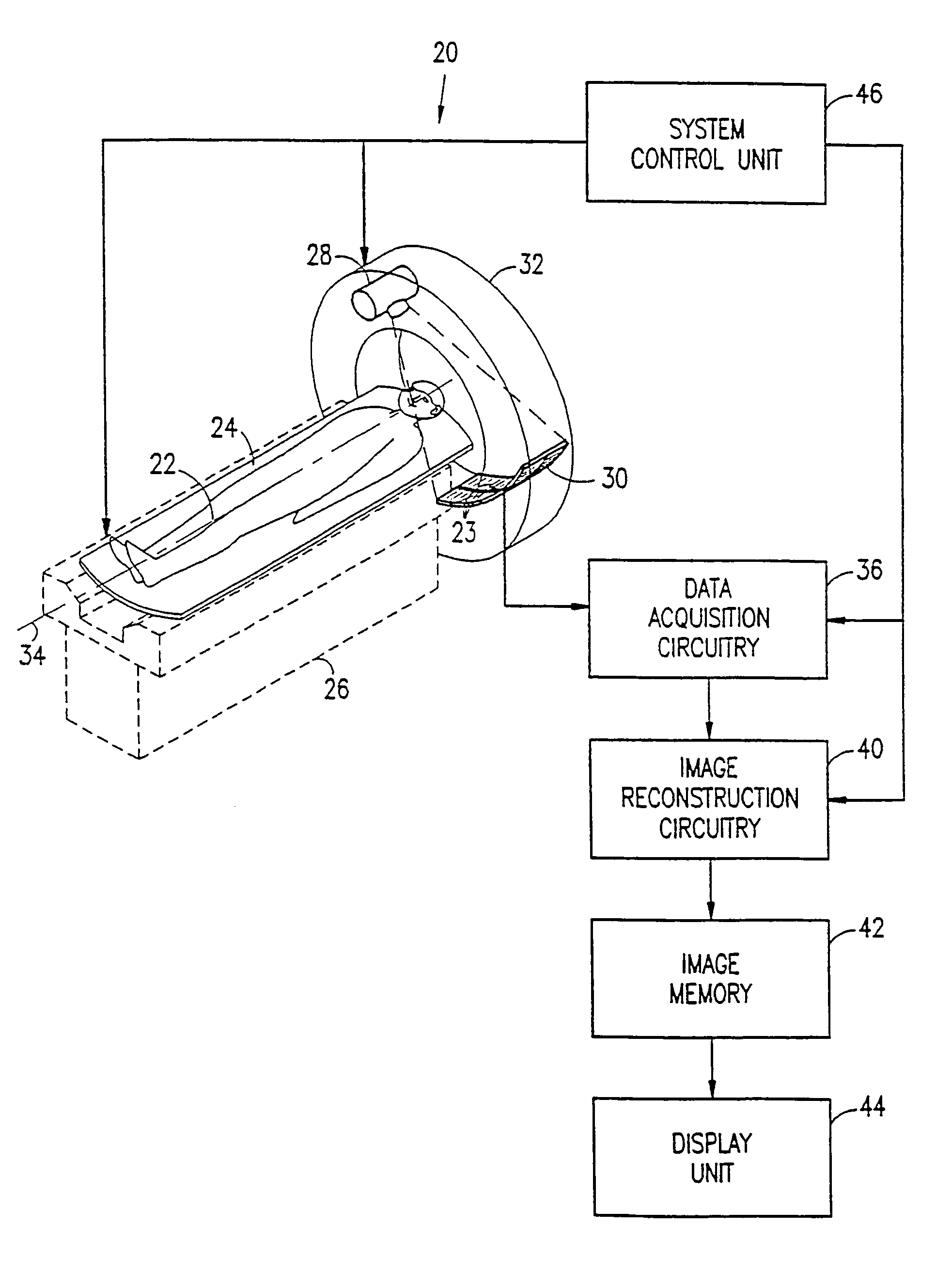
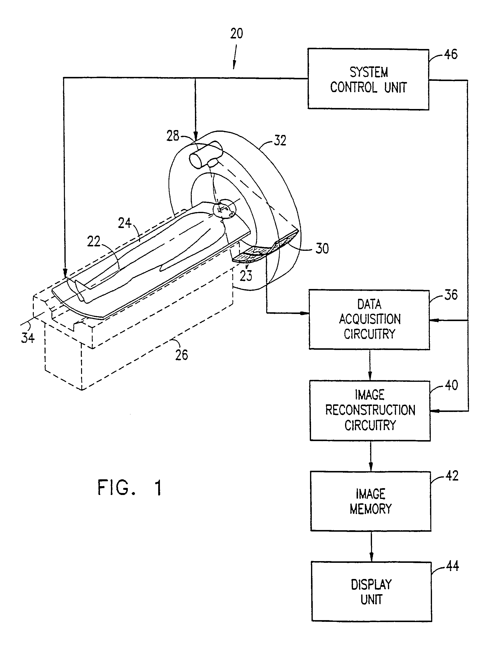
[0072]Reference is now made to FIG. 1, which shows a CT scanner 20, operative in accordance with a preferred embodiment of the present invention. Scanner 20 comprises a bed 24, supported by a base 26, on which bed a subject 22 lies while his body is being imaged by the scanner. Scanner 20 further comprises an X-ray tube 28, which irradiates subject 22, and a detector array 30, which receives X-rays from tube 28 and generates signals responsive to the attenuation of the X-rays in passing through the subject's body. Preferably, array 30 comprises multiple, parallel rows of X-ray detector elements 23. Alternatively, array 30 may comprise only a single row of detector elements.

[0073]Tube 28 and array 30 are mounted on an annular gantry 32, so as to revolve about subject 22. Bed 24 is advanced through gantry 32 along an axis 34, taken to be the Z-axis of a scanning coordinate system. Z-axis 34 is generally parallel to the long axis of the subject's body. Scanner 20 preferably operates in...


PUM


Abstract

A method for modifying a planar image slice in a CT scanner having a predetermined reconstruction angle, comprising: reconstructing an image of the slice using initial X-ray attenuation data acquired along an initial scan path sector; acquiring additional X-ray attenuation data along an additional scan path sector in a vicinity of the axial position of the slice, the sector having an angular extent substantially less than the reconstruction angle; and modifying the image, to provide a modified image of the slice, responsible to the additional attenuation data.

Description

RELATED APPLICATION[0001]This application is a US National filing of PCT Application PCT / IL98 / 00074, filed Feb. 12, 1998.FIELD OF THE INVENTION[0002]The present invention relates generally to computerized tomographic (CT) imaging, and specifically to CT imaging of dynamic physiological processes and interventional procedures.BACKGROUND OF THE INVENTION[0003]CT scanners are well known in the art. Generally, such scanners comprise an X-ray tube, mounted on an annular gantry, so as to revolve about a subject being imaged. The subject lies on a bed, which is translated through the gantry. The axis of translation of the bed (conventionally the Z-axis) is generally parallel to the long axis of the subject's body, which is typically perpendicular to the plane of revolution of the tube.[0004]An array of X-ray detectors on the opposite side of the subject from the X-ray tube receive radiation transmitted through the subject. The detectors generate signals proportional to the attenuated X-ray...

Claims


Application Information

Patent Timeline
Patent Type & Authority Patents(United States)
IPC IPC(8): A61B6/03A61B6/12
CPCA61B6/032A61B6/027Y10S128/922
Inventor DAFNI, EHUDSHRETER, URIGELMAN, HAIM
Owner MARCONI MEDICAL SYST ISRAEL
Why Eureka
Try Eureka