Gas operated action for auto-loading firearms

a gas-operated action and firearm technology, applied in the field of firearms, can solve the problems of inability to conveniently store or transport the assembled rifle, and inability to meet the needs of a 0.50 cal, etc., to achieve the effect of the associated material and manufacturing costs, reducing wear over time, and reducing the size of the gun receiver

Active Publication Date: 2005-12-06
BENDER TERRENCE
View PDF16 Cites 132 Cited by
  • Summary
  • Abstract
  • Description
  • Claims
  • Application Information

AI Technical Summary

Benefits of technology

[0015]Secondly, it should be possible to turn the semi-auto gas assist off and cycle the rifle manually by pulling on the same charging handle in the new and improved concept, something that is not possible with the “AR-15” concept. This is desirable for accuracy driven applications that allow operation of the rifle like a bolt-action without having to remove the rifle from the shoulder, or take the eyes off the target.
[0027]The implementation of these design objectives is a rifle with the following features: a removable barrel assembly that attaches directly to the receiver tube with a threaded barrel nut for compact storage or stowage; a receiver that has a general cylindrical shape for easy machining; a tubular receiver with thick walls to allow for the attachment of the lower receiver by threaded fasteners; a tubular receiver with thick walls to allow for the machining of a slot for the stable reception of a detachable box magazine; a tubular receiver with thick walls to allow for the attachment of a fixed propellant gas-elbow that is attached with threaded fasteners to the receiver and is received internally by the bolt-carrier; a tubular receiver with thick walls that allows attachment of an accessory mount with threaded fasteners that contains features to mount an optical target scope, etc., to hold the bolt-carrier in an “open” position, to direct propellant gases from the barrel gas transfer tube to the propellant gas-elbow, to hold a gas meter screw that allows adjustment of the gas flow to the bolt-carrier; a tubular receiver with thick walls to allow for the machining of a long rectangular ejection port that also serves as the slot feature for the bolt charging handle key that prevents the bolt-carrier from rotating without unduly weakening the receiver tube; a rod that is fixed in a rearward position with respect to the receiver tube and always passes through the bolt-carrier and the bolt cam pin locking the rotational position of the bolt only when it is not in battery; a lower receiver that contains the fire control mechanism and is generally a rectangular shape; a bolt and bolt-carrier with an integral piston-cylinder pressure chamber; a bolt with battery locking lugs that can be rotated with a cam pin by a helical cam slot in the bolt-carrier; a gas plumbing system that does not require an “AR-15” type carry handle or other features that would add to the size, weight, or manufacturing expense of the gun; a suite of major machined features comprising a useful net shape that requires only simple lathe turning and end milling operations; and finally, a large caliber rifle that is as small and light as practical.

Problems solved by technology

The overall length of the assembled rifle may be too large to conveniently case for storage or transportation.
This is not practical for a 0.50 cal.
Secondly, it should be possible to turn the semi-auto gas assist off and cycle the rifle manually by pulling on the same charging handle in the new and improved concept, something that is not possible with the “AR-15” concept.

Method used


Image

  • Gas operated action for auto-loading firearms
  • Gas operated action for auto-loading firearms
  • Gas operated action for auto-loading firearms

Examples


Embodiment Construction

[0068]While this invention may be embodied in many different forms, there are described in detail herein specific preferred embodiments of the invention. This description is an exemplification of the principles of the invention and is not intended to limit the invention to the particular embodiments illustrated.

[0069]For the purposes of this disclosure, like reference numerals in the figures shall refer to like features unless otherwise indicated.

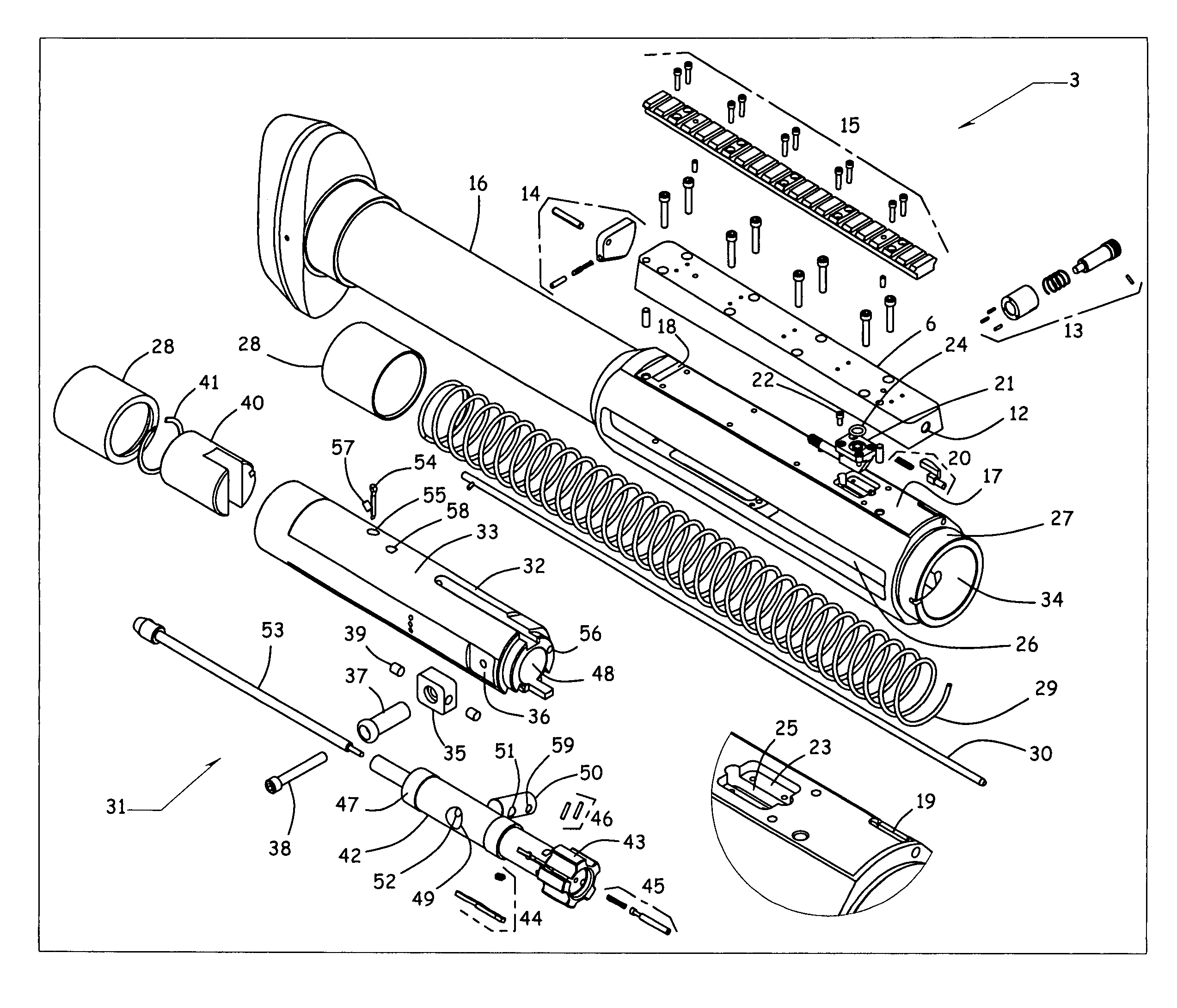
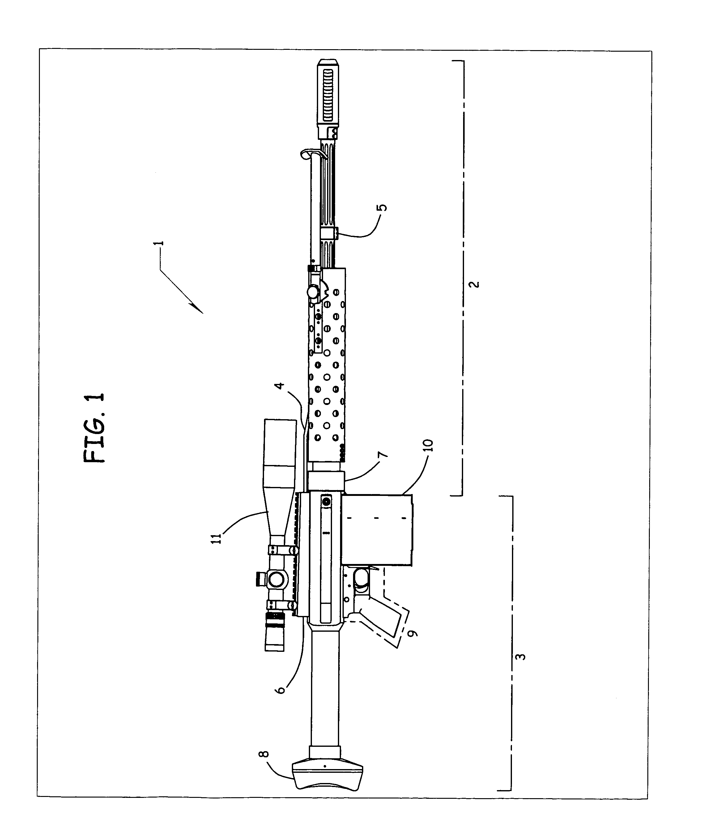
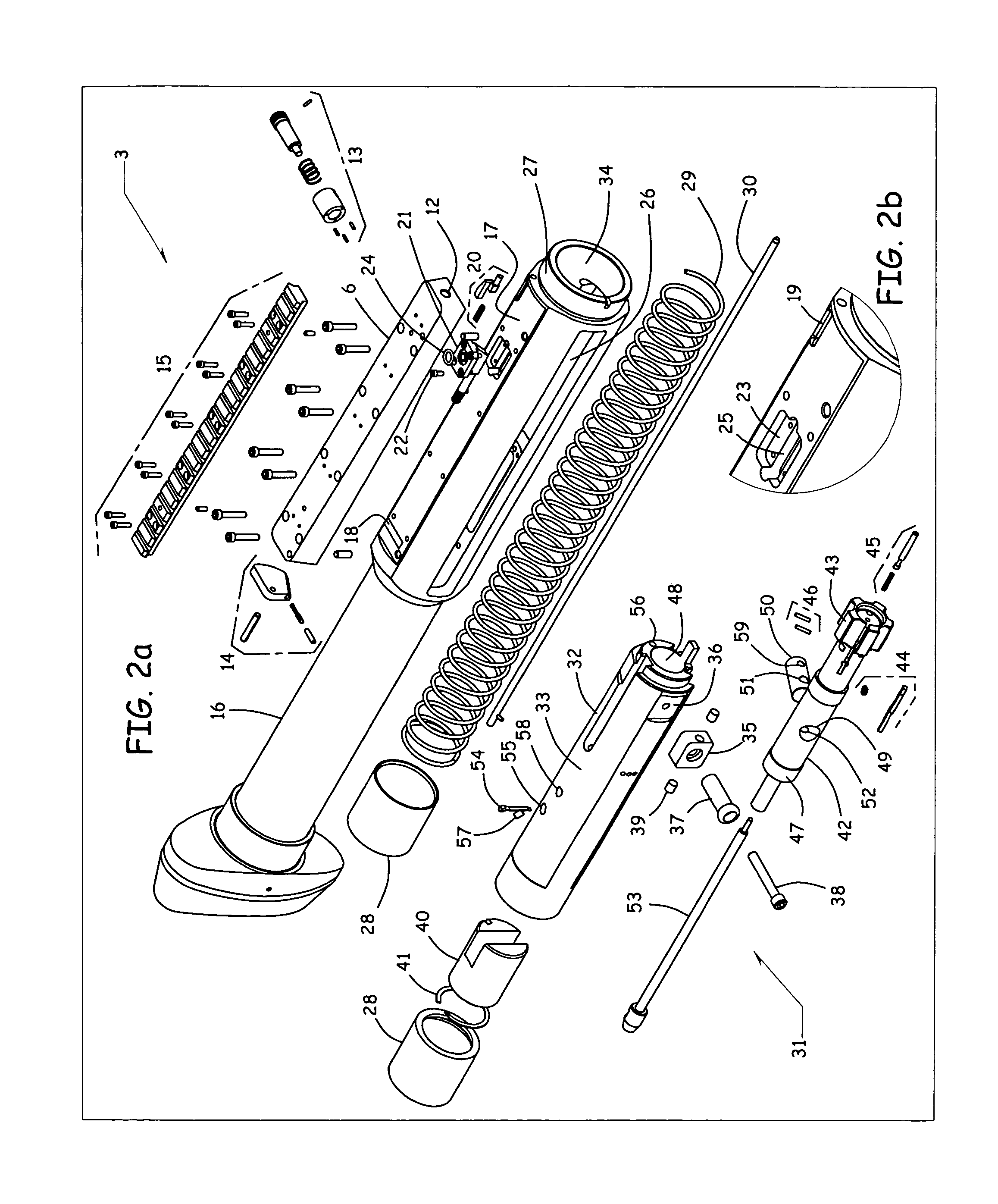
[0070]The preferred embodiment of the present invention is evident in a rifle 1 shown in FIG. 1. The rifle 1 comprises two major subassemblies, the barrel subassembly 2 in a forward position and the receiver assembly 3 in a rearward position, which positional convention is hereinafter made by frequent reference.

[0071]The barrel assembly 2 is conspicuous with a gas tube 4. Said gas tube 4 directs propellant gas from a cross-hole port in the barrel wall nearer its muzzle through a barrel gas collar means 5 (not shown in detail) into the recei...


PUM


Abstract

A gas operated action for auto-loading guns may comprise a receiver, a biasing spring, a bolt-carrier reciprocable within the receiver, a bolt having a cam pin, and an action rod fixedly attached to the receiver. The cam pin may engage the action rod during recoil travel of the bolt and bolt-carrier, thereby preventing rotation of the bolt when the cam pin is engaged with the action rod.

Description

CROSS-REFERENCE TO RELATED APPLICATIONS[0001]This application claims the benefit of Provisional Patent Application No. 60 / 442,760 filed Jan. 27, 2003, the entire contents of which are incorporated herein by reference.TECHNICAL FIELD[0002]This invention relates to firearms for firing projectiles, and more specifically, in some embodiments, to shoulder-fired auto-loading, or semiautomatic rifles. In some embodiments, this invention is a propellant gas assisting cycling breech unlocking and locking system adapted for large calibers.BACKGROUND OF THE INVENTION[0003]All US patents and applications and all other published documents mentioned anywhere in this application are incorporated herein by reference in their entirety.[0004]Without limiting the scope of the invention, a brief summary of some of the claimed embodiments of the invention is set forth below. Additional details of the summarized embodiments of the invention and / or additional embodiments of the invention may be found in t...

Claims


Application Information

Patent Timeline
Patent Type & Authority Patents(United States)
IPC IPC(8): F41A3/00F41A3/36F41A5/24F41F5/00
CPCF41A3/36F41A5/24
Inventor BENDER, TERRENCE
Owner BENDER TERRENCE
Why Eureka
Try Eureka