Accessible ceiling grid system

a grid system and ceiling technology, applied in the field of suspended ceiling systems, can solve the problems of time-consuming, difficult and time-consuming processes for tightening the screws necessary to hold the grid system together, and difficult to plan the placement of ladder sections, so as to achieve accurate panel positioning, easy removal, and durable construction

Inactive Publication Date: 2005-12-06
OWENS CORNING INTELLECTUAL CAPITAL LLC
View PDF35 Cites 52 Cited by
  • Summary
  • Abstract
  • Description
  • Claims
  • Application Information

AI Technical Summary

Benefits of technology

[0016]An embodiment of the present invention provides a cruciform grid main in a grid system that has an alignment fin for accurate panel positioning.
[0017]An embodiment of the present invention provides a grid system having a spacer bar that can be moved laterally to avoid obstructions in the ceiling.
[0018]An embodiment of the present inv

Problems solved by technology

Moreover, attaching the butterfly clip 230 to T-bar 250 (i.e., the alignment of the holes, etc.) must be conducted at the job site because shipping the T-bars 250, 250a installed would take up too much room and would therefore make shipping difficult.
This is particularly disadvantageous if an obstruction (e.g., a sprinkler) is present in

Method used


Image

  • Accessible ceiling grid system
  • Accessible ceiling grid system
  • Accessible ceiling grid system

Examples


Embodiment Construction

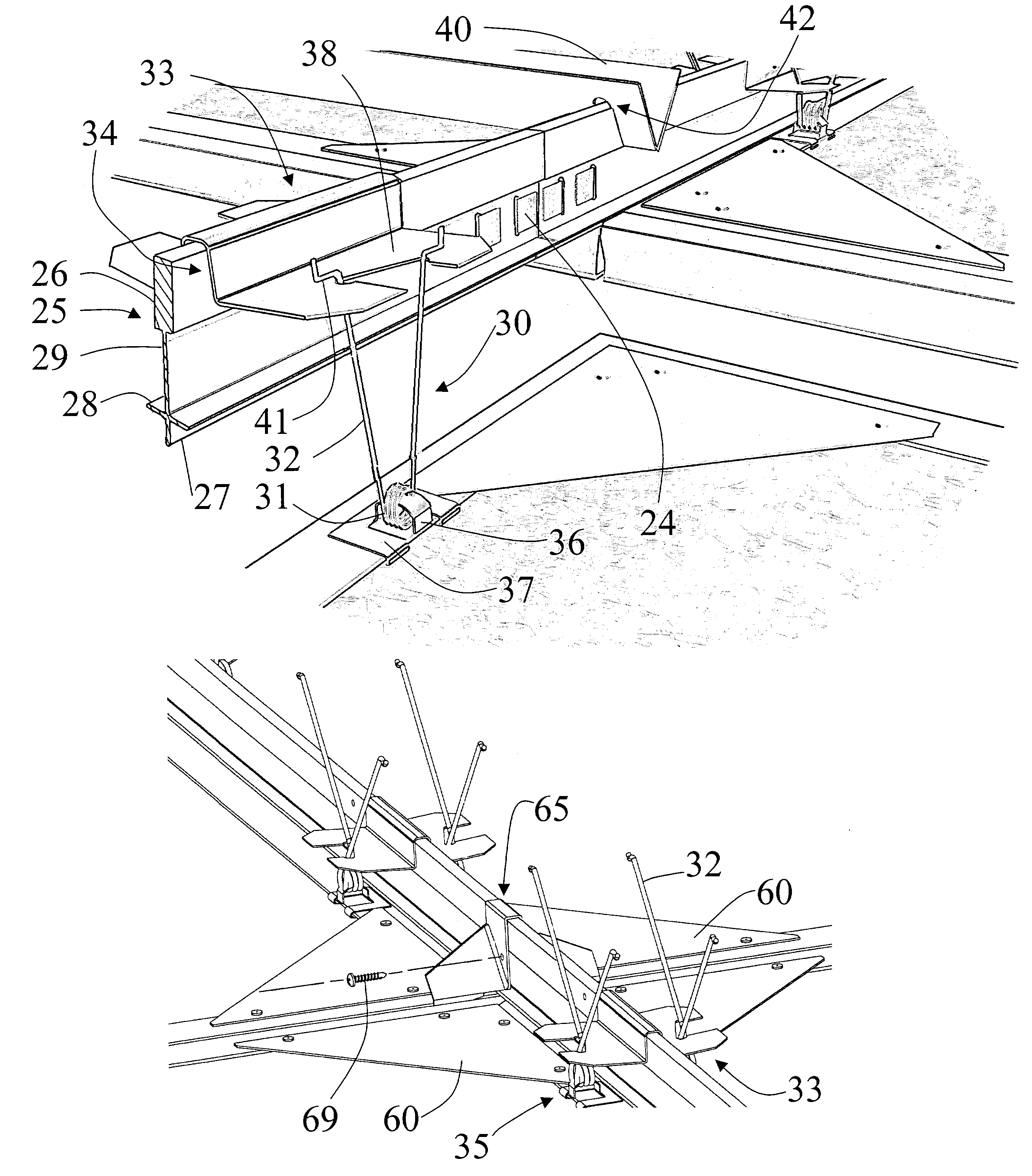
[0035]Referring now to FIGS. 3–10, the grid system for torsion spring mounting according to embodiments of the present invention can best be seen. In grid system 20, the cruciform grid mains 25 are hung from the ceiling from wires 21 in a conventional manner and connected end to end by a grid main connector (not shown). To attach the grid main connector (not shown) to the cruciform grid mains, tabs 24 of the grid main connector are inserted into corresponding slots 46 in the cruciform grid mains 25. The grid main connector is fastened to the cruciform grid mains 25 by bending the tabs 24 until they are flush with the cruciform main grid 25. Preferably, each connector has four tabs 24.

[0036]Each cruciform grid main 25 is formed of a bulb 26 attached to a web 29, a pair of arms 28 extending laterally from the web 29, and an alignment fin 27 extending from the web. The bulb 26 is formed of a large size, e.g., ⅝″, which provides a large contact surface for the attachment of the side loa...


PUM


Abstract

A grid system for torsion spring mounting of aluminum-framed panels is provided which includes a plurality of main grid beams and spacer bars. The main grid beams support a side load mounting clip formed with a slot in the side of the side load mounting clip to engage a torsion spring held by a spring retainer clip such that the panel is supported by the torsion spring. Disengagement of the torsion springs lowers the panels and permits access to the ceiling grid system above the panel members. In a preferred embodiment, the panel has a multifaceted profile including an edge surface that abuts a corresponding edge surface on an adjacent panel. The peripheral edges of the adjacent panel members diverge above the abutting edge surfaces to accommodate either the alignment fin or the tab of the tile stop and diverge below the abutting edge surfaces to form a reveal.

Description

TECHNICAL FIELD AND INDUSTRIAL APPLICABILITY OF THE INVENTION[0001]The present invention relates generally to the field of suspended ceiling systems, and more particularly a grid system for torsion spring mounting of aluminum-framed panels.BACKGROUND OF THE INVENTION[0002]Referring to FIGS. 1–2, a three-quarter perspective view showing a typical conventional torsion spring type suspended ceiling system is depicted. As shown in FIG. 1, grid system 1 includes a plurality of ceiling panels 2 that are supported by a grid 4. Torsion springs 12, 12a hold each panel 2 against a foot portion 4a of the support grid 4. Panel 2a is depicted as being in the open or partially disconnected position. In this embodiment, torsion springs 12a are shown in the disengaged position relative to butterfly clips 6. Torsion springs 12 of panel 2a are disconnected from their corresponding butterfly clips (not shown). The dangling ceiling panel 2a shows that each panel 2 has a metal frame 8 around its circumf...

Claims


Application Information

Patent Timeline
IPC IPC(8): E04B9/00E04B9/12E04B9/16E04B9/26
CPCE04B9/003E04B9/125E04B9/16E04B9/225E04B9/26
Inventor KLIEGLE, DENNISALTER, HARRY A.
Owner OWENS CORNING INTELLECTUAL CAPITAL LLC
Why Eureka
Try Eureka