Venetian blind cutting machine

a cutting machine and venetian blind technology, applied in the field of venetian blind cutting machines, can solve the problems of time and laborious adjustment of the blind carriage, complicated to change the blind locating assembly of venetian blinds, etc., and achieve the effect of lifting/lowering the blind carriag

Inactive Publication Date: 2005-12-06
IND TECH RES INST +1
View PDF11 Cites 40 Cited by
  • Summary
  • Abstract
  • Description
  • Claims
  • Application Information

AI Technical Summary

Benefits of technology

[0010]According to a first embodiment of the present invention, the carriage driving mechanism uses a reversible motor to rotate a double-thread screw rod, causing two movable screw nuts to move two pair of links and to further lift / lower the blind carriage.
[0011]According to a second embodiment of the present invention, air cylinders are used to reciprocate two slides on two parallel sliding rails, causing the slides to move two pairs of links and to further lift / lower the blind carriage.

Problems solved by technology

It is complicated to change the blind locating assembly of a Venetian blind.
Because the elevation adjustment structure of the blind carriage is adjusted manually, the adjustment of the blind carriage takes much time and labor.

Method used


Image

  • Venetian blind cutting machine
  • Venetian blind cutting machine
  • Venetian blind cutting machine

Examples


Embodiment Construction

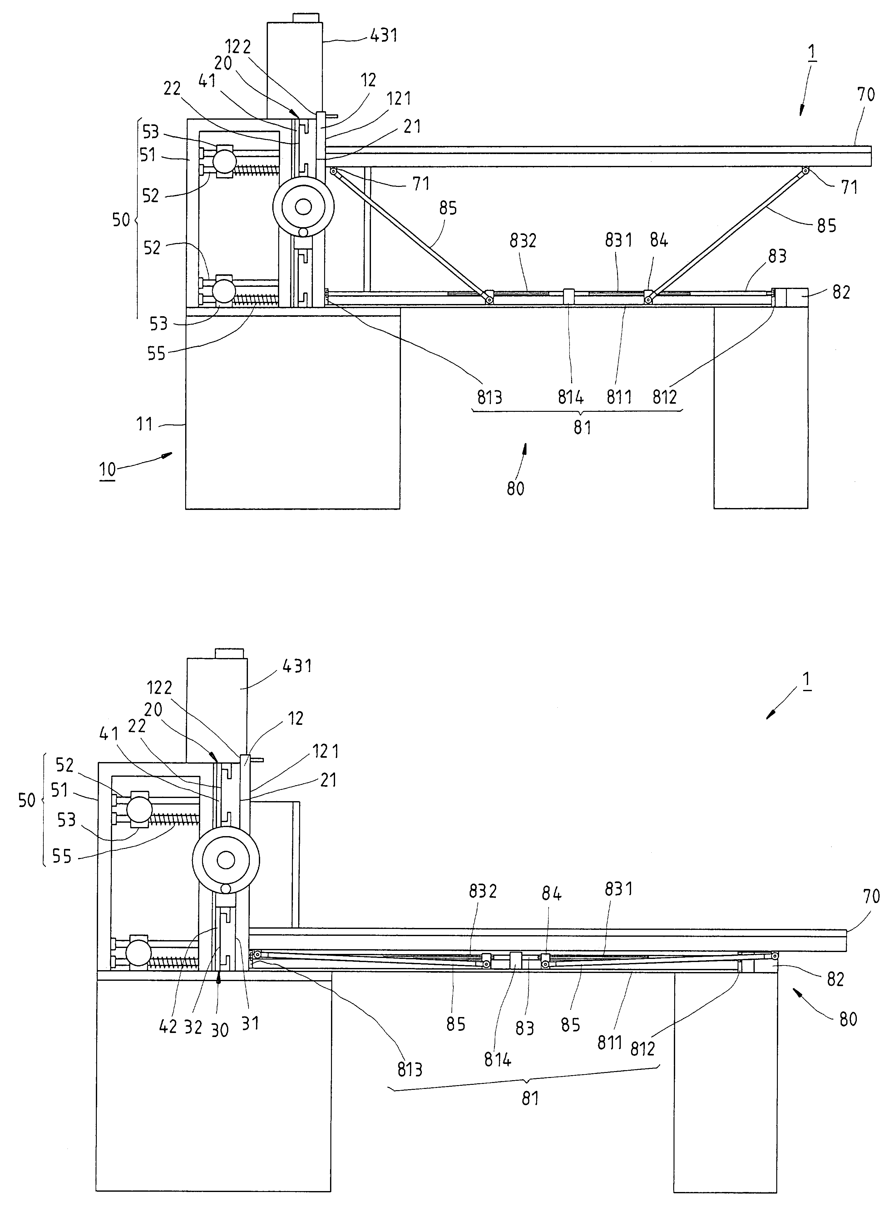
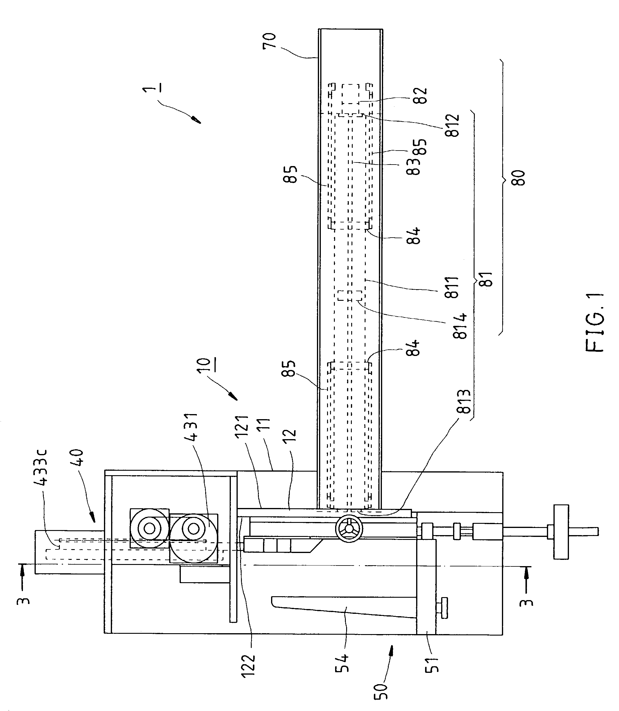
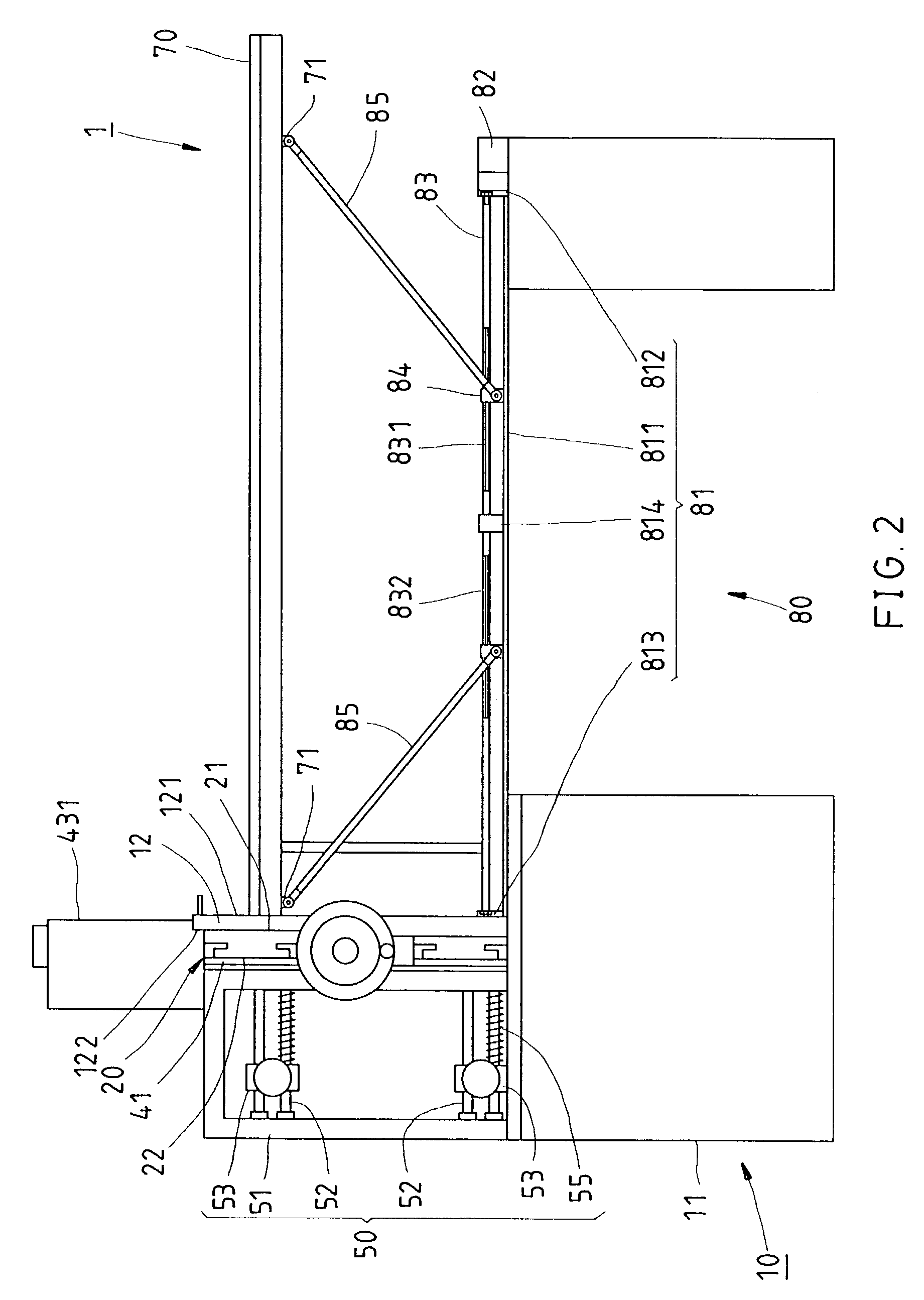
[0019]Referring to FIGS. 1˜3, a Venetian blind cutting machine 1 in accordance with the first preferred embodiment of the present invention is shown comprised of a machine base 10, two blind locating modules, namely, the first blind locating module 20 and the second blind locating module 30, a cutter unit 40, a limiter 50, and a die block adjustment mechanism 60.

[0020]The machine base 10 comprises a base support frame 11, and a vertical mount 12 located on the top side of the base support frame 11. The vertical mount 12 has a first side 121, a second side 122 opposite to the first side 121, and two openings (not shown) cut through the first side 121 and the second side 122 at different elevations.

[0021]The blind locating modules 20 and 30 each have a first side 21 or 31, a second side 22 or 32 opposite to the first side 21 or 31, through holes 23 or 33, and die blocks 24 or 34. The through holes 23 and 33 of the blind locating modules 20 and 30 are made subject to the cross-sections...


PUM

PropertyMeasurementUnit
elevationaaaaaaaaaa
lengthaaaaaaaaaa
elevationsaaaaaaaaaa

Abstract

A Venetian blind cutting machine is constructed to include a machine base, two blind locating modules mounted on the machine base at different elevations, each of which having a set of through holes for supporting component parts of a Venetian blind to be cut, a blind carriage adapted to carry the Venetian blind to be cut, a carriage for moving the blind carriage to the elevation of one of the blind locating modules for enabling the Venetian blind to be cut to be put in the selected blind locating module for cut, a cutter provided at the other side of the blind locating modules, and a cutter drive adapted to move the cutter across the imaginary axis passing through each of the through holes of the blind locating modules to cut the component parts of the loaded Venetian blind and then to return the cutter after cutting.

Description

BACKGROUND OF THE INVENTION[0001]1. Field of the Invention[0002]The present invention relates to a Venetian blind cutting machine adapted to cut the headrail, bottom rail, and slats of a Venetian blind to the desired length and, more particularly, to such a Venetian blind cutting machine, which has means to lift / lower the Venetian blind to be cut automatically to the desired elevational cutting position.[0003]2. Description of the Related Art[0004]A variety of Venetian blind cutting machines have been disclosed and have appeared on the market. Similar designs are seen in U.S. Pat. Nos. 5,799,557; 5,927,172; 6,089,302. These Venetian blind cutting machines commonly comprise a blind locating assembly having through holes for supporting the headrail, bottom rail, and slats of a Venetian blind to be cut, a cutter, and an air cylinder or reversible motor adapted to drive the cutter to cut the parts of the Venetian blind to the desired length. These Venetian blind cutting machines are com...

Claims


Application Information

Patent Timeline
Patent Type & Authority Patents(United States)
IPC IPC(8): B23D23/00B26D1/09E06B9/266
CPCB23D23/00B26D1/09E06B9/266Y10T83/412Y10T83/6476Y10T83/654Y10T83/6563Y10T83/75Y10T83/8756Y10T83/8858
Inventor LIN, JUNG-KUEILIU, KUEI-LU
Owner IND TECH RES INST
Why Eureka
Try Eureka