
Electromagnetic servo valve strategy for controlling a free piston engine

a technology of servo valves and free pistons, which is applied in the direction of engine starters, machines/engines, electric motor starters, etc., can solve the problems of partial vacuum in the cylinder, pistons can collide with the cylinder head or with another piston, and the air charge will leak through the inlet and exhaust ports and across the piston rings. to achieve the effect of increasing the kinetic energy, increasing the pressure in the combustion chamber, and limiting the displacement of the piston

Inactive Publication Date: 2005-12-06
FORD GLOBAL TECH LLC
View PDF10 Cites 12 Cited by
  • Summary
  • Abstract
  • Description
  • Claims
  • Application Information

AI Technical Summary

Benefits of technology

The invention is a method for controlling a servo that applies a force to a piston in a free piston engine. The method includes determining the length of a response period for the actuator force to reach a desired magnitude after applying a control signal to the servo. The method ensures that the actuator force is switched to the first state when the length of time for the piston to move from its current position to the desired position reaches the length of the response period. The technical effect of this invention is to improve the control of the actuator force in a free piston engine, ensuring efficient and reliable operation.

Problems solved by technology

If the engine is stopped with a piston in the compression stroke, leakage of the air charge from the cylinder through inlet and exhaust ports and across the piston rings will occur during the shutdown period due to the pressure in the cylinder.
This leakage can produce a partial vacuum in the cylinder.
When the engine is restarted without a sufficient volume of air in each cylinder, a piston can collide with the cylinder head or with another piston in the same cylinder because of the air spring provides insufficient resistance to piston displacement.

Method used


Image

  • Electromagnetic servo valve strategy for controlling a free piston engine
  • Electromagnetic servo valve strategy for controlling a free piston engine
  • Electromagnetic servo valve strategy for controlling a free piston engine

Examples


Embodiment Construction

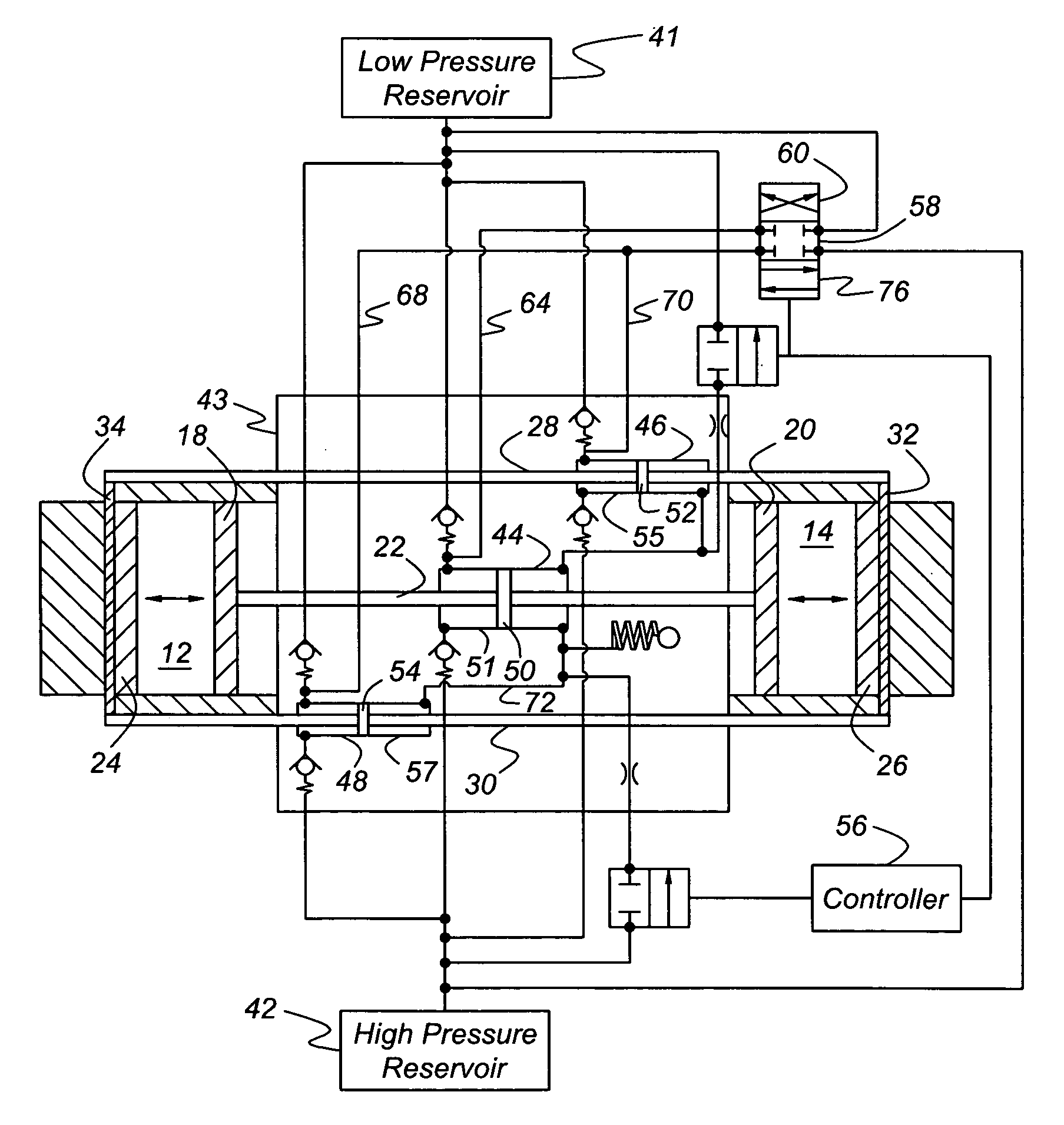
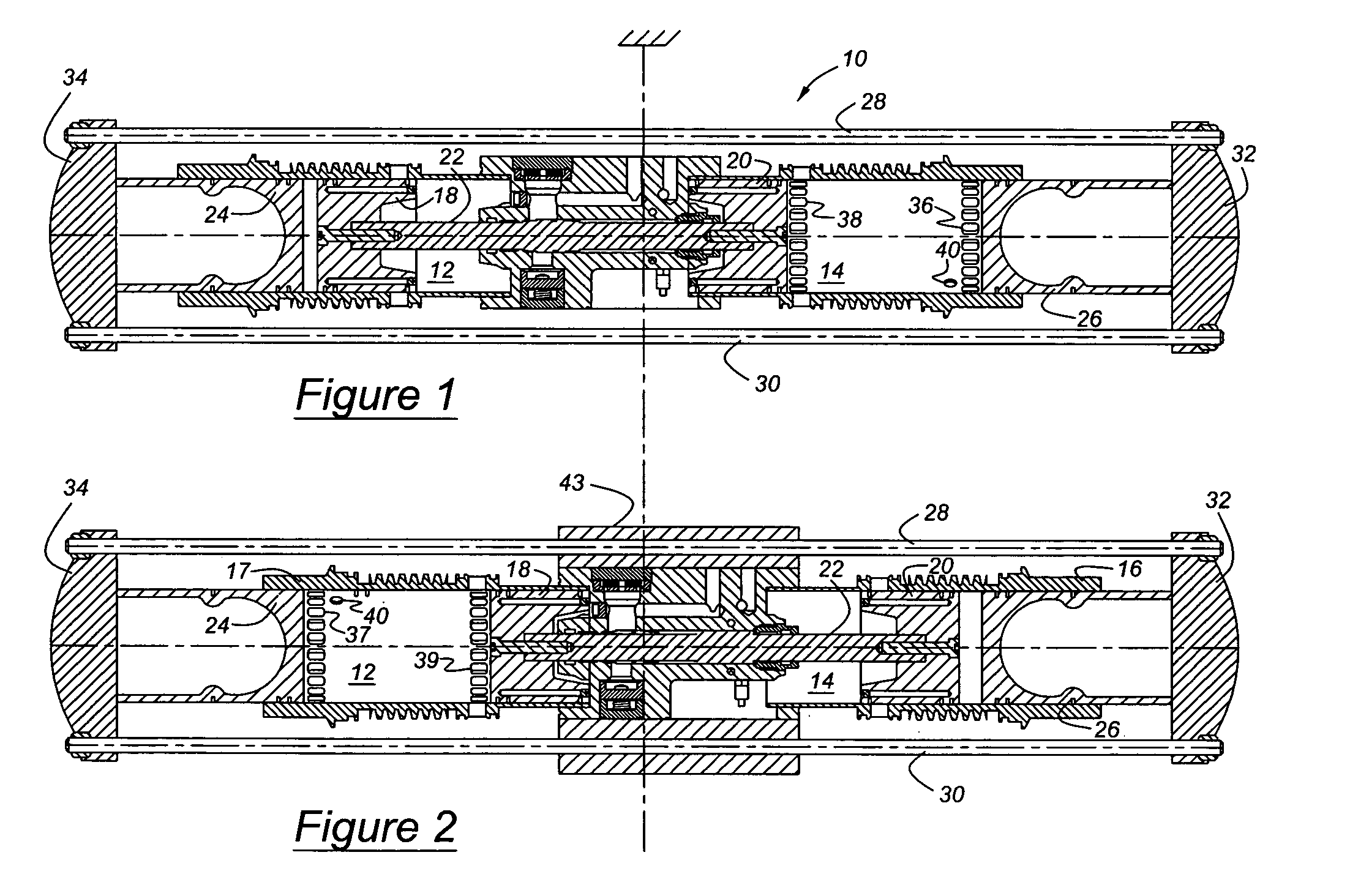
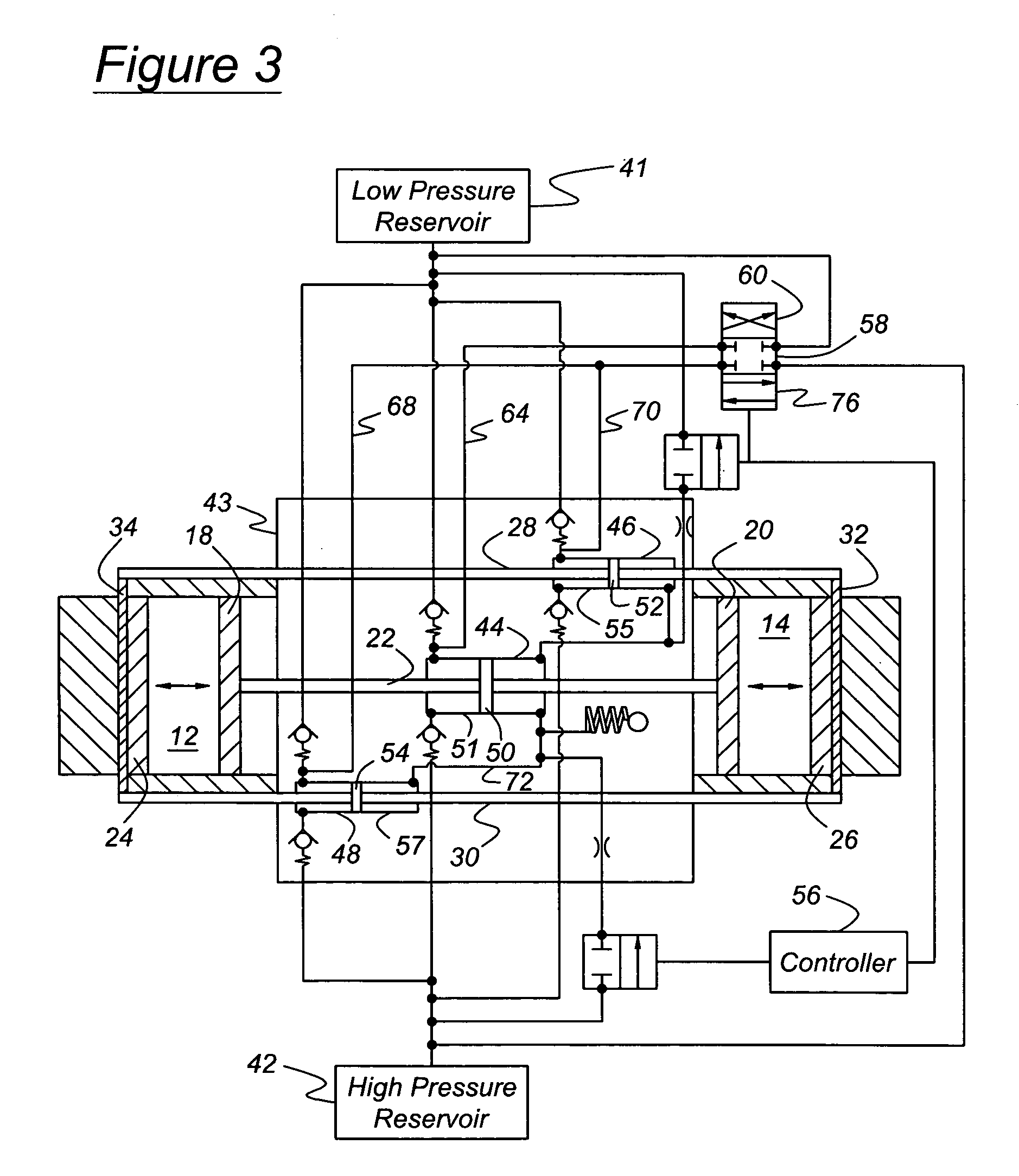
[0021]Referring first to FIGS. 1 and 2, a free piston engine 10 includes a first cylinder 12 and a second cylinder 14, axially aligned with the first cylinder, the cylinders being located in cylinder liners or engine blocks 16, 17. A first pair of pistons, inner pistons 18, 20, are mutually connected by a push rod 22. A first piston 18 of the first piston pair reciprocates within the first cylinder 12, and the second piston 20 of the first piston pair reciprocates within the second cylinder 14. A second pair of pistons, outer piston 22, 24, are connected mutually by pull rods 28, 30, secured mutually at the axial ends of pistons 24, 26 by bridges 32, 34. A first piston of the second or outer piston pair reciprocates within the first cylinder 12, and a second piston 26 of the outer piston pair reciprocates within the first cylinder 14. Each cylinder 12, 14 is formed with air inlet ports 36, 37 and exhaust ports 38, 39. In FIG. 1, the ports 37, 39 of cylinder 12 are closed by pistons ...


PUM


Abstract

A method for controlling a servo for an actuator that applies a force to a piston that reciprocates in a cylinder of a free piston engine having axially-aligned cylinders and a pair of mutually connected pistons that reciprocate in the cylinders. The servo has a first state at which an energy source is connected to the actuator for developing the actuating force. The length of a response period for the actuator force to reach a desired magnitude after applying a control signal to the servo is determined. The length of a period for the piston to reach a desired position where the actuator force will reach the desired magnitude is determined. The servo is switched to the first state when the length of time for the piston to move from its current position to the desired position reaches the length of the response period.

Description

BACKGROUND OF THE INVENTION[0001]The invention relates to internal combustion engines. In particular, the invention pertains to controlling the application and magnitude of a periodic force applied by an actuator that reciprocates a piston while starting a free piston engine.[0002]A free piston internal combustion engine includes one or more reciprocating pistons located in a combustion cylinder. But there is no crankshaft mutually connecting the pistons and causing them to reciprocate when actuated by a starter-alternator, as in a conventional internal combustion engine. In a free piston engine running under normal operation, each piston moves during an expansion stroke in its cylinder in response to forces produced by combustion of an air-fuel mixture in the cylinder. Pressure produced by combustion in one cylinder is used to compress an air-fuel charge in another cylinder. Before combustion occurs while starting the engine, an actuating system is be used to compress the air-fuel ...

Claims


Application Information

Patent Timeline
Patent Type & Authority Patents(United States)
IPC IPC(8): F02B71/00F02B71/02F02N11/00
CPCF02B71/00F02B71/02
Inventor JANSSEN, HENDRIKUS
Owner FORD GLOBAL TECH LLC
Learn More