Fuel vapor treatment system for internal combustion engine

a technology for internal combustion engines and treatment systems, which is applied in the direction of combustion-air/fuel-air treatment, electric control, instruments, etc., can solve the problems of difficult to accurately measure the flow rate of air-fuel vapor mixtures, difficult to accurately control the air-fuel ratio, and difficult to accurately measure the fuel vapor concentration in the control of air-fuel ratios

Active Publication Date: 2005-12-06
DENSO CORP +1
View PDF12 Cites 77 Cited by
  • Summary
  • Abstract
  • Description
  • Claims
  • Application Information

AI Technical Summary

Benefits of technology

[0008]The present invention has been accomplished in view of the above-mentioned problems and it is an object of the invention to provide a fuel vapor treatment system for an internal combustion engine which can measure the concentration of fuel vapor promptly and accurately and which thereby can purge fuel vapor efficiently and control the air-fuel ratio properly.
[0013]Since the measurement passage is provided, the concentration of fuel vapor is detected without flowing gas through the purging passage. Therefore, it is not necessary to determine the concentration of fuel vapor during purge, and the air-fuel ratio can be controlled properly while purging fuel vapor efficiently.

Problems solved by technology

Therefore, it has been difficult to measure with a high accuracy the flow rate of an air-fuel vapor mixture of which concentration is not constant like the purged gas.
However, in the case of an engine having a small intake pipe volume or in an operation region of a high flow velocity of intake air, the time required for purged fuel vapor to reach the injection position is shorter than the time required for completing the measurement of a fuel vapor concentration and thus it is hard to reflect a properly measured fuel vapor concentration in the control of air-fuel ratio.
Without purge restriction, it is difficult to control the air-fuel ratio properly.
Particularly, when a fuel vapor treatment system is to be applied to a hybrid vehicle which has recently been spotlighted, it is absolutely necessary to carry out a large quantity purge for the recovery of adsorption capacity because of the opportunity of purging is limited.

Method used


Image

  • Fuel vapor treatment system for internal combustion engine
  • Fuel vapor treatment system for internal combustion engine
  • Fuel vapor treatment system for internal combustion engine

Examples


first embodiment

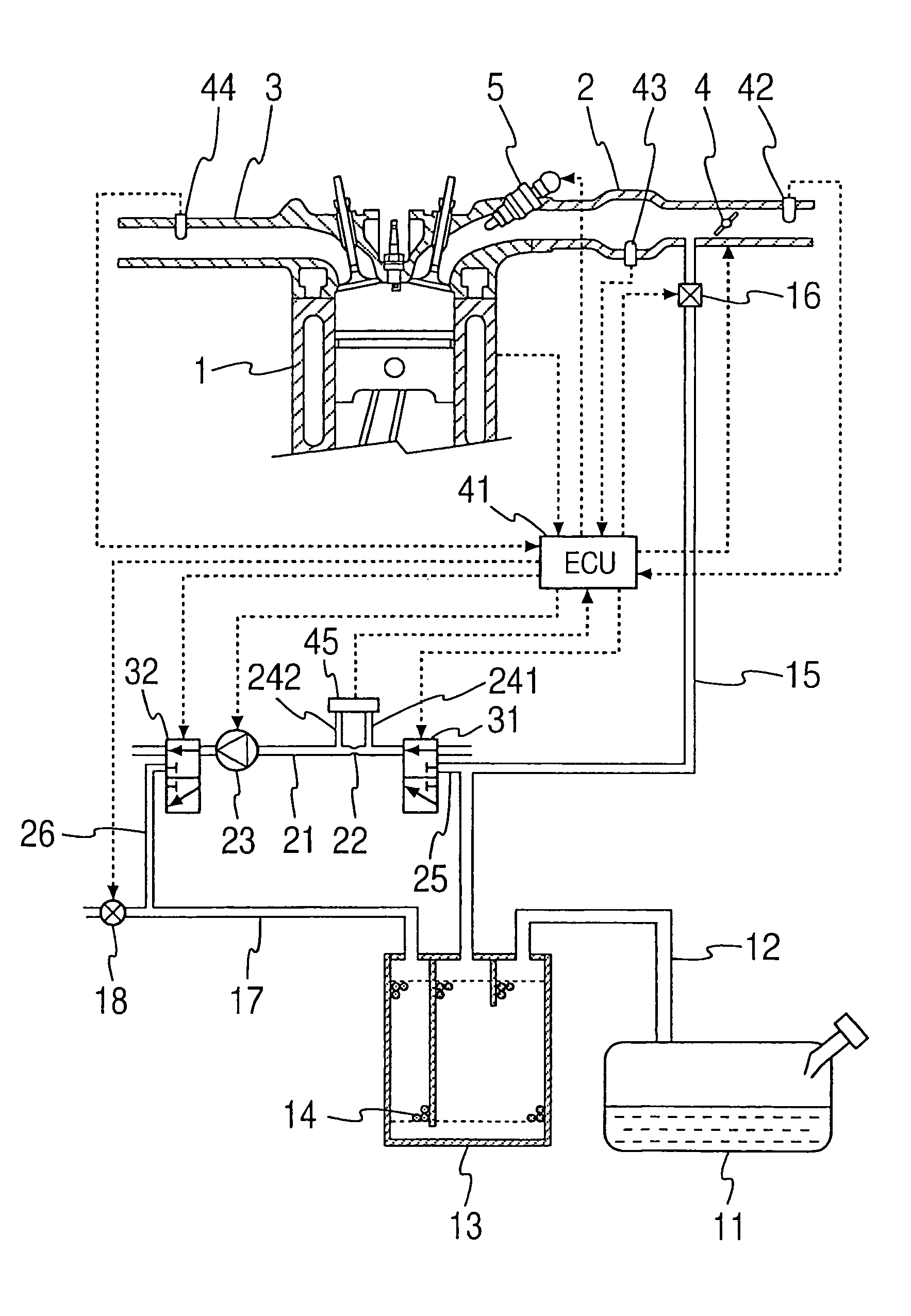
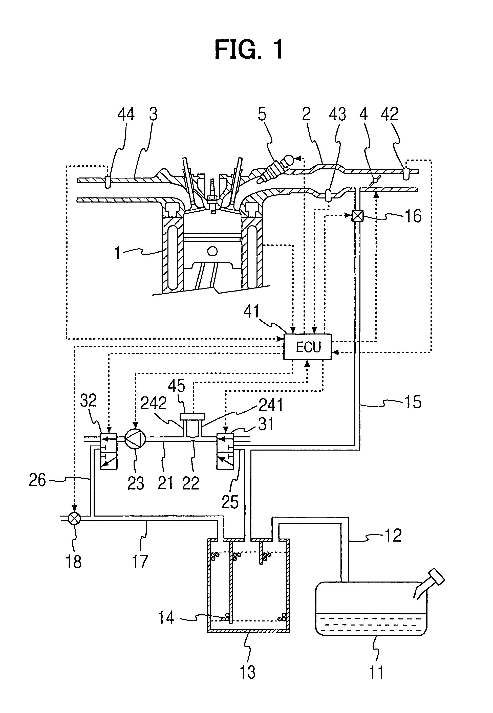
[0056]FIG. 1 shows the construction of a fuel vapor treatment system according to a first embodiment of the present invention. This embodiment is the application of the present invention to a vehicular engine. A fuel tank 11 for an internal combustion engine 1, which is referred to as an engine 1 hereinafter, is connected to a canister 13 through an inlet passage 12. The fuel tank 11 and the canister 13 are constantly in communication with each other. An adsorbing material 14 is loaded into the canister 13 to temporarily adsorb fuel evaporated within the fuel tank 11. The canister 13 is connected to an intake pipe 2 in the engine 1 through a purging passage 15. A purge valve 16 as a purge control valve is disposed in the purging passage 15. The canister 13 and the intake pipe 2 come into communication with each other, when the purge valve 16 is opened.

[0057]The purge valve is an electromagnetic valve, of which opening degree is adjusted by, for example, duty control with use of an e...

second embodiment

[0108]FIG. 16 shows the construction of an engine according to a second embodiment of the present invention. This construction corresponds to a replacement of a part of the construction of the first embodiment by another construction. Portions which perform substantially the same operations as in the first embodiment are identified by the same reference numerals as in the first embodiment and a description will be given below mainly about the difference from the first embodiment.

[0109]A bypass 27 is provided for connecting the fuel vapor passage 21 and the purged air passage 17 directly with each other without interposition of the pump 23 and the second switching valve 32. One end of the bypass 27 is in communication with the fuel vapor passage 21 at a position between the orifice 22 and the pump 23, while an opposite end thereof is in communication with the purging passage 17 on the canister 13 side rather than the branch passage 26. A bypass opening / closing valve 28 is disposed in...

third embodiment

[0120]FIG. 22 shows the construction of an engine according to a third embodiment of the present invention. In the same figure, a combination (“evaporative system” hereinafter) of structural members located in the range from the canister 13 up to the fuel tank 11 via the inlet passage 12 and up to the purge valve 16 via the purging passage 15 forms a closed space capable of diffusing fuel vapor when the purge valve 16 is closed. According to the associated regulation in the U.S., the installation of a troubleshooting device is obliged for checking whether fuel vapor is leaking or not in the evaporative system (“leak check” hereinafter). This embodiment corresponds to a replacement of a part of the second embodiment by another construction so that the leak check can be done in a simple manner. Portions which perform substantially the same operations as in the previous embodiments are identified by the same reference numerals as in the previous embodiments and a description will be gi...


PUM


Abstract

A pump generates a gas flow within a measurement passage having an orifice. A differential pressure sensor detects a pressure difference between both ends of the orifice. Switching valves are disposed in the measurement passage to create a first concentration measurement state in which the measurement passage is opened at both ends thereof and the gas flowing through the measurement passage is the atmosphere, and a second concentration measurement state in which the measurement passage is in communication at both ends thereof with a canister and the gas flowing through the measurement passage is a fuel vapor-containing air-fuel mixture provided from the canister. An ECU calculates a fuel vapor concentration by based on a pressure difference detected in the first concentration measurement state and a pressure difference detected in the second concentration measurement state.

Description

CROSS-REFERENCE TO RELATED APPLICATION[0001]This application is based on Japanese Patent Applications No. 2004-89033 filed on Mar. 25, 2004, No. 2004-326562 filed on Nov. 10, 2004, and No. 2004-377452 filed on Dec. 27, 2004, the disclosures of which are incorporated herein by reference.FIELD OF THE INVENTION[0002]The present invention relates to a fuel vapor treatment system for an internal combustion engine.BACKGROUND OF THE INVENTION[0003]The fuel vapor treatment system restricts the dissipation of fuel vapor produced in a fuel tank to the atmosphere. A fuel vapor introduced into the system from the fuel tank through an inlet passage is once adsorbed into an adsorbing material disposed within a canister and, when an internal combustion engine operates, the adsorbed fuel vapor is purged to an intake pipe in the internal combustion engine through a purging passage by utilizing a negative pressure developed within the intake pipe. The adsorption capacity of the adsorbing material is ...

Claims


Application Information

Patent Timeline
Patent Type & Authority Patents(United States)
IPC IPC(8): F02D41/02F02D45/00F02M25/07F02M25/08F02M33/02
CPCF02M25/0809F02M25/0827F02M25/0872F02M25/089
Inventor AMANO, NORIYASUKAWANO, TAKANOBUINAGAKI, KOICHIKOYAMA, NOBUHIKOKANO, MASAOTAKAKURA, SHINSUKEYAMADA, YOSHICHIKA
Owner DENSO CORP
Why Eureka
Try Eureka