Fuel vapor treatment system for internal combustion engine
a technology for internal combustion engines and treatment systems, which is applied in the direction of combustion-air/fuel-air treatment, electric control, instruments, etc., can solve the problems of difficult to accurately measure the flow rate of air-fuel vapor mixtures, difficult to properly control the air-fuel ratio, and difficult to measure the concentration of fuel vapor in the control of air-fuel ratios. achieve the effect of purging fuel vapor efficiently
- Summary
- Abstract
- Description
- Claims
- Application Information
AI Technical Summary
Benefits of technology
Problems solved by technology
Method used
Image
Examples
first embodiment
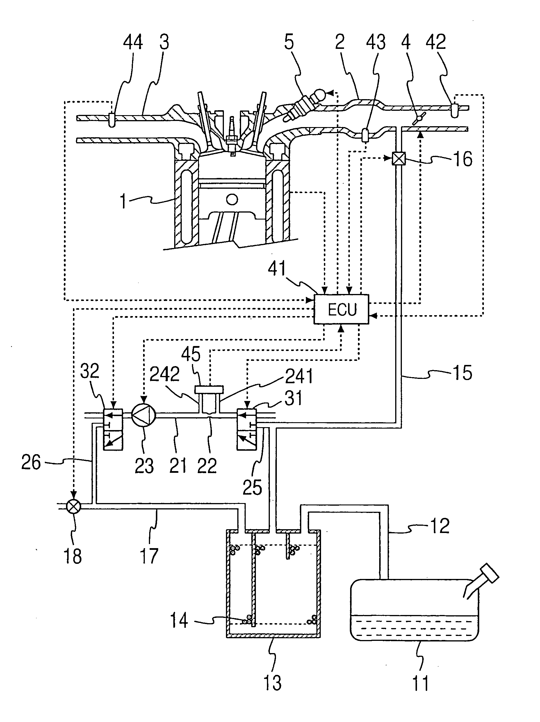
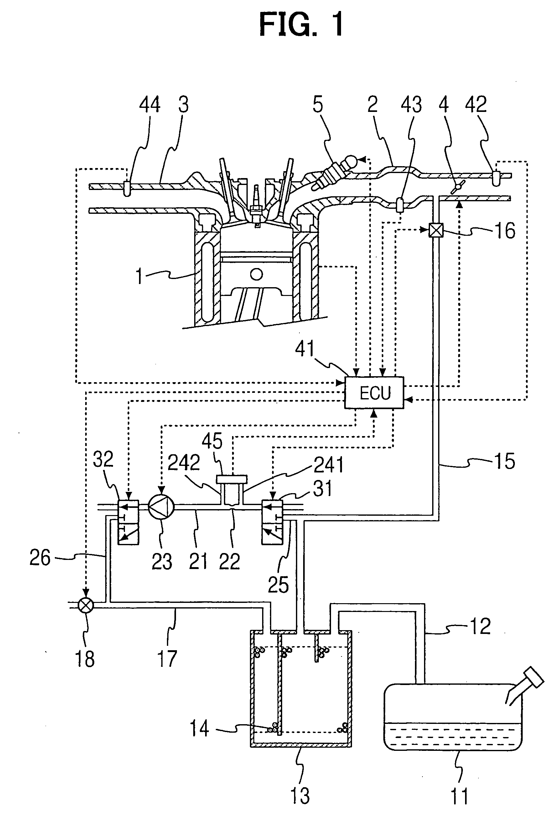
[0056]FIG. 1 shows the construction of a fuel vapor treatment system according to a first embodiment of the present invention. This embodiment is the application of the present invention to a vehicular engine. A fuel tank 11 for an internal combustion engine 1, which is referred to as an engine 1 hereinafter, is connected to a canister 13 through an inlet passage 12. The fuel tank 11 and the canister 13 are constantly in communication with each other. An adsorbing material 14 is loaded into the canister 13 to temporarily adsorb fuel evaporated within the fuel tank 11. The canister 13 is connected to an intake pipe 2 in the engine 1 through a purging passage 15. A purge valve 16 as a purge control valve is disposed in the purging passage 15. The canister 13 and the intake pipe 2 come into communication with each other, when the purge valve 16 is opened.
[0057] The purge valve is an electromagnetic valve, of which opening degree is adjusted by, for example, duty control with use of an...
second embodiment
[0107]FIG. 16 shows the construction of an engine according to a second embodiment of the present invention. This construction corresponds to a replacement of a part of the construction of the first embodiment by another construction. Portions which perform substantially the same operations as in the first embodiment are identified by the same reference numerals as in the first embodiment and a description will be given below mainly about the difference from the first embodiment.
[0108] A bypass 27 is provided for connecting the fuel vapor passage 21 and the purged air passage 17 directly with each other without interposition of the pump 23 and the second switching valve 32. One end of the bypass 27 is in communication with the fuel vapor passage 21 at a position between the orifice 22 and the pump 23, while an opposite end thereof is in communication with the purging passage 17 on the canister 13 side rather than the branch passage 26. A bypass opening / closing valve 28 is disposed ...
third embodiment
[0119]FIG. 22 shows the construction of an engine according to a third embodiment of the present invention. In the same figure, a combination (“evaporative system” hereinafter) of structural members located in the range from the canister 13 up to the fuel tank 11 via the inlet passage 12 and up to the purge valve 16 via the purging passage 15 forms a closed space capable of diffusing fuel vapor when the purge valve 16 is closed. According to the associated regulation in the U.S., the installation of a troubleshooting device is obliged for checking whether fuel vapor is leaking or not in the evaporative system (“leak check” hereinafter). This embodiment corresponds to a replacement of a part of the second embodiment by another construction so that the leak check can be done in a simple manner. Portions which perform substantially the same operations as in the previous embodiments are identified by the same reference numerals as in the previous embodiments and a description will be gi...
PUM
 Abstract
Description
Claims
Application Information
 - R&D
- Intellectual Property
- Life Sciences
- Materials
- Tech Scout
- Unparalleled Data Quality
- Higher Quality Content
- 60% Fewer Hallucinations
Browse by: Latest US Patents, China's latest patents, Technical Efficacy Thesaurus, Application Domain, Technology Topic, Popular Technical Reports.
© 2025 PatSnap. All rights reserved.Legal|Privacy policy|Modern Slavery Act Transparency Statement|Sitemap|About US| Contact US: help@patsnap.com


