Flexible conduit, particularly for sanitary purposes

a flexible conduit technology, applied in the direction of rigid pipes, pipe elements, domestic plumbing, etc., can solve the problems of inability to choose, excessive stiffness of connections, etc., and achieve the effect of reducing the cross-sectional flow area of the conduit, strengthening and sealing the material-to-material bond of the conduit components at the ends of the conduit, and improving the strength and seal of the material-to-material bond

Inactive Publication Date: 2005-12-06
VOHRAN PATENTVERW
View PDF11 Cites 17 Cited by
  • Summary
  • Abstract
  • Description
  • Claims
  • Application Information

AI Technical Summary

Benefits of technology

[0023]According to a further advantageous feature of the invention the strength and seal of the material-to-material bond of the conduit components at the ends of the conduit may be further improved by providing, in addition to an outer sleeve surrounding the coupling part, an inner sleeve positioned inside the plastic inner hose. The inner sleeve, when introduced into the plastic inner hose has an outer diameter that equals the inner diameter of the plastic inner hose. Subsequently the inner sleeve is radially expanded such that its inner diameter will not be smaller than the original inner diameter of the plastic inner hose. In this manner the coupling part is compressed between the inner sleeve, the plastic inner hose, the jacketed metal hose and the outer sleeve without necessitating a reduction in the cross-sectional flow area of the conduit.

Problems solved by technology

The choice of material for the coupling component to be injection molded, the plastic jacket of the metal hose and the plastic inner hose may be made from the large group of polyolefins, including polyethylene and polypropylene; such a choice is not possible in case of known plastic conduits which have a PVC component.
Such an attachment would, among others, result in the disadvantage of an excessive stiffness of the connection.

Method used


Image

  • Flexible conduit, particularly for sanitary purposes
  • Flexible conduit, particularly for sanitary purposes

Examples


Embodiment Construction

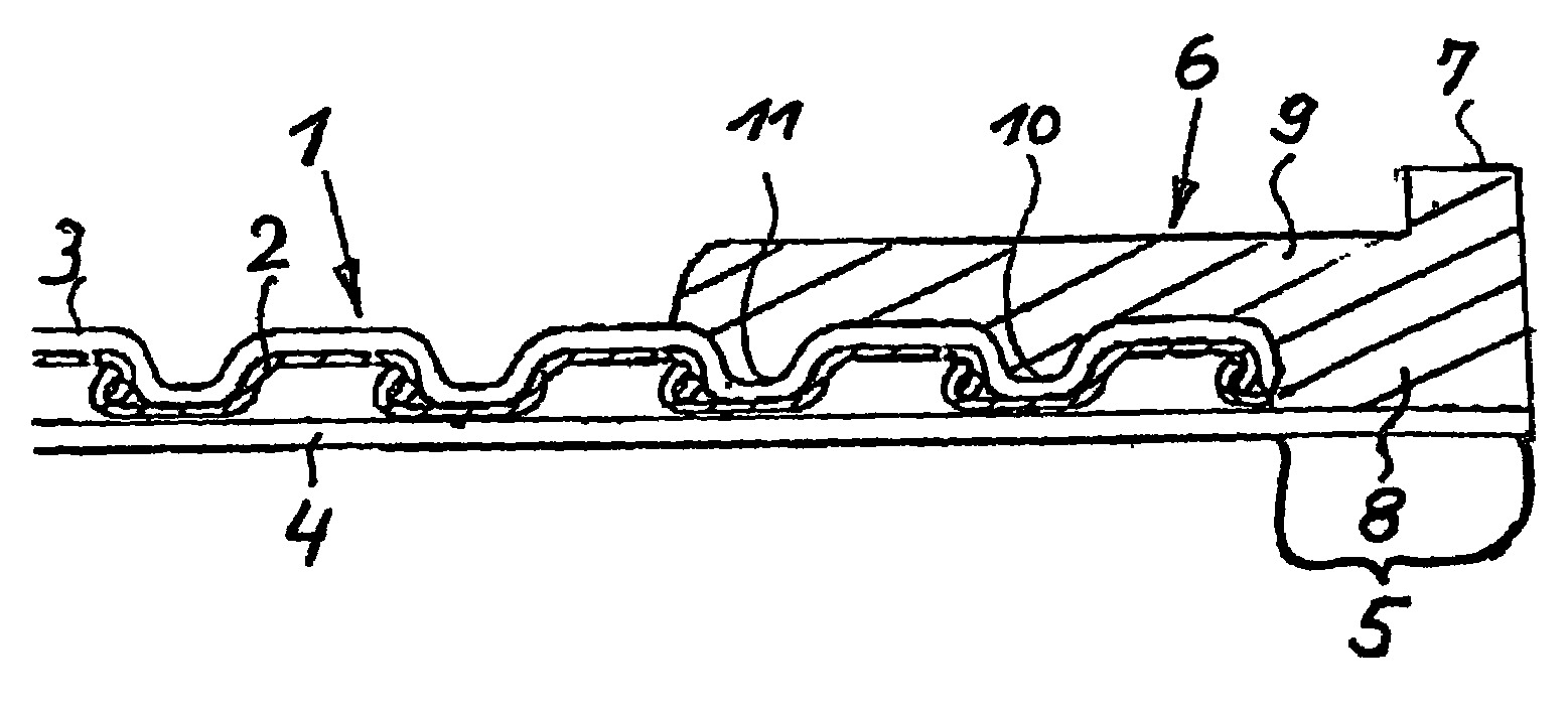
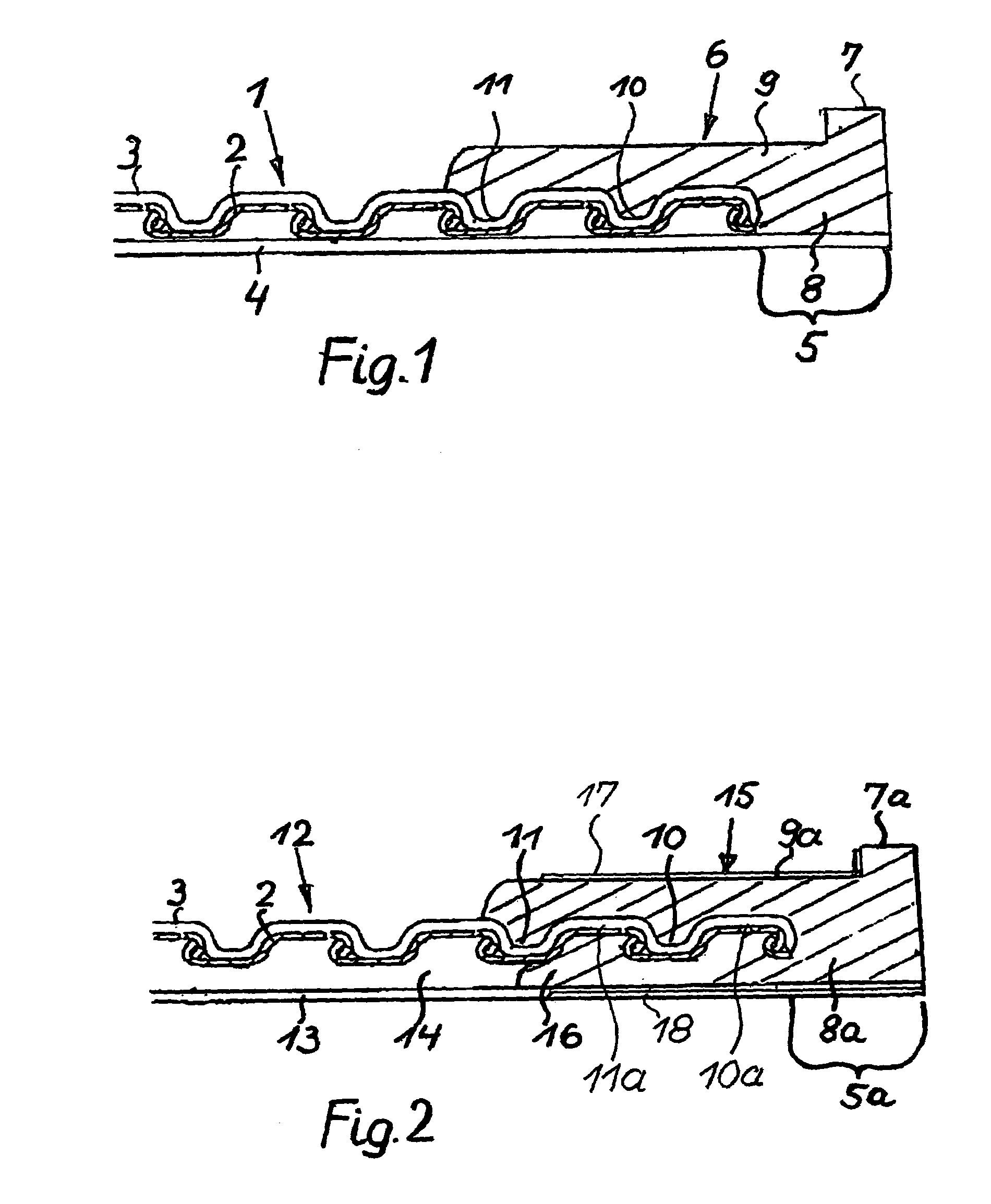
[0026]The flexible conduits of the two embodiments of the invention to be described hereafter in conjunction with FIGS. 1 and 2, respectively, find particular use as shower hoses.

[0027]Turning to the first preferred embodiment illustrated in FIG. 1, the flexible conduit generally designated at 1 includes a metal hose 2 of helically wound construction. The metal hose 2 accommodates a plastic inner hose 4 such that the latter projects with a hose portion 5 beyond an end of the metal hose 2. The outer diameter of the plastic inner hose 4 is only slightly smaller than the inner diameter of the metal hose 2 to ensure that the plastic inner hose 4, as illustrated, practically lies against the inside of the metal hose 2.

[0028]To obtain a resistant, smooth, non-metallic outer surface for the flexible conduit 1, the metal hose 2 is provided with a jacket 3 made, in particular, of transparent polyurethane. Expediently, the plastic inner hose 4 is also made of polyurethane. To ensure a highly ...


PUM

PropertyMeasurementUnit
axial lengthaaaaaaaaaa
flexibleaaaaaaaaaa

Abstract

A flexible conduit includes a metal hose provided with a helical groove having a plurality of turns; a plastic jacket surrounding the metal hose and conforming to the helical groove thereof; a plastic inner hose received in the metal hose and having a projecting length portion extending beyond an end of the metal hose. The conduit further includes a plastic coupling part which surrounds the metal hose. The coupling part includes a cylindrical collar surrounding the projecting length portion and having a material-to-material bond therewith; and an overlapping portion adjoining the cylindrical collar and extending away therefrom. The overlapping portion surrounds the jacket and extends into the helical groove. The overlapping portion and the plastic jacket have a material-to-material bond with one another.

Description

BACKGROUND OF THE INVENTION[0001]This invention relates to a flexible conduit, particularly for sanitary use, and is of the conventional type that has a helically grooved metal hose, a plastic inner hose loosely received in the metal hose and a plastic coupling part which is welded (injection molded) to the plastic inner hose. The coupling part has a sleeve-like overlapping portion which overlaps the metal hose and which at least indirectly projects into the helical groove of the metal hose.[0002]Helically grooved metal hoses which are flexible due to their construction are widely used and they particularly excel because of their robust nature. In particular, in the sanitary field chromium-plated or colored metal hoses have been used as shower hoses or generally as sanitary hoses.[0003]As described, for example, in German Patent Document No. 298 07 448 U1, the conduit includes an outer metal hose provided with a helical groove and a plastic inner hose (for example., a PVC hose) loos...

Claims


Application Information

Patent Timeline
Patent Type & Authority Patents(United States)
IPC IPC(8): E03C1/02F16L33/00F16L9/06F16L9/14F16L11/15F16L33/28
CPCE03C1/021E03C1/025F16L11/15Y10S285/903
Inventor VOHRER, CHRISTOPH
Owner VOHRAN PATENTVERW
Why Eureka
Try Eureka