Eureka AIR delivers breakthrough ideas for toughest innovation challenges, trusted by R&D personnel around the world.

Completion apparatus and methods for use in wellbores

a technology for cement shoes and assembly, which is applied in the direction of drilling casings, wellbore/well accessories, pipes, etc., can solve the problems of increasing the outer diameter, the accumulation of unwanted materials, and the failure of subsequent drilling of cement shoes to remove some residual material from the lower portion of the string, so as to prevent accumulation of unwanted materials

Inactive Publication Date: 2005-12-06
WEATHERFORD TECH HLDG LLC
View PDF59 Cites 13 Cited by
  • Summary
  • Abstract
  • Description
  • Claims
  • Application Information

AI Technical Summary

Benefits of technology

The present invention provides a way to prevent cement and other unwanted materials from accumulating in the lower part of a tubular with a larger inner diameter. This is done by using a sleeve that is placed at the end of the tubular and expanded to cover the larger diameter area. The sleeve can be dissolvable or deformable with a ring. It can also be retrievable from the surface of the well. This invention helps to keep the tubular clean and free of debris.

Problems solved by technology

Once the cementing is completed, the shoe and any cement remaining in the casing can later be destroyed when the wellbore is drilled to a new depth.
One problem with monobore wells relates to the difficulty of expanding one tubular into another when the outer tubular is cemented into the wellbore, preventing the outer diameter from increasing as the inner tubulars is expanded into it.
Because of the enlarged inner diameter portion of the first string, subsequent drilling of the cement shoe is usually inadequate to remove some residual material from the lower portion of the string.
The residual material can interfere with the connection between the upper end of the next string of tubulars and the lower end of the existing string.
Additionally, the residual material may extend into the bore and interfere with wellbore components that are run-in into the wellbore.

Method used


Image

  • Completion apparatus and methods for use in wellbores
  • Completion apparatus and methods for use in wellbores
  • Completion apparatus and methods for use in wellbores

Examples


Embodiment Construction

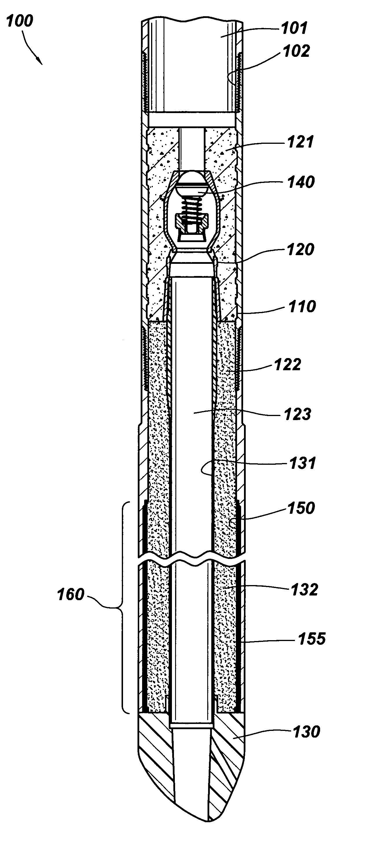
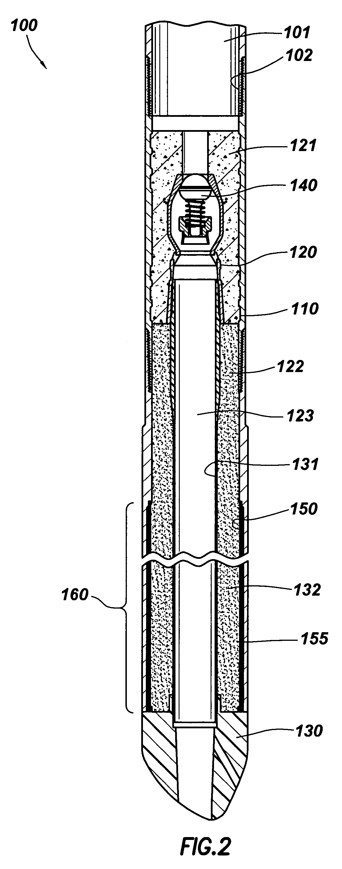
[0025]FIG. 2 is a cross-sectional view of a cement shoe assembly 100 disposed at a lower end of a tubular 101 and having a housing 110 that includes an enlarged inner diameter portion 160 at a lower end. The assembly 100 is typically disposed at a lower end of a string of tubulars that is run into a well and cemented. The cement isolates the wellbore from the formation therearound and prevents the wellbore from collapsing. The assembly 100 is preferably connected to a tubular 101 by a threaded connection 102 formed therebetween. The cement shoe assembly 100 includes a drillable shoe portion 120 disposed within the housing 110. The drillable shoe portion 120 includes a longitudinal bore 123 extending through the center of the cement shoe assembly 100 and provides a fluid path for the cement. The bore 123 communicates with the tubular 101 through a biased, one way valve 140 disposed at the upper end of the bore 123. The valve 140 permits fluid to enter the assembly 100 but prevents we...


PUM


Abstract

An apparatus and methods for preventing the accumulation of unwanted materials in an enlarged inner diameter portion of a casing or housing. In one aspect of the invention, a sleeve is disposed in the housing to isolate an annular area defined by the outer surface sleeve and the wall of the enlarged inner diameter portion. The sleeve prevents unwanted materials from being disposed in the annular area. The sleeve can later be expanded into the enlarged inner diameter portion, removed from the wellbore or destroyed. In another aspect of the invention, the sleeve is provided and disposed to cover the enlarged inner diameter portion. By covering the enlarged inner diameter portion, unwanted material is prevented from accumulating at said portion and from interfering with the expansion of the next casing into said portion to form a monobore. The sleeve can be made from materials that are dissolvable, elastically deformable, or retrievable.

Description

CROSS-REFERENCE TO RELATED APPLICATIONS[0001]This application is a continuation of U.S. patent application Ser. No. 09 / 918,002, filed Jul. 30, 2001, U.S. Pat. No. 6,655,459 which is herein incorporated by reference.BACKGROUND OF THE INVENTION[0002]1. Field of the Invention[0003]The present invention provides an apparatus and methods for use in wellbores. More particularly, the invention provides an apparatus and methods for use with a cement shoe assembly having an isolation sleeve for use in monobore wells. Even more particularly, the invention provides a cement shoe assembly with an enlarged inner diameter portion and a sleeve for isolating the enlarged portion from the bore of the cement shoe, thereby facilitating the expansion of a tubular into the enlarged portion after cementing. The invention also provides an isolation sleeve for use with a casing in a monobore well.[0004]2. Description of the Related Art[0005]In the drilling of a hydrocarbon well, a wellbore is formed using ...

Claims


Application Information

Patent Timeline
Patent Type & Authority Patents(United States)
IPC IPC(8): E21B17/14E21B43/10
CPCE21B17/14E21B43/10E21B43/103E21B43/106
Inventor MACKAY, ALEXANDER CRAIG
Owner WEATHERFORD TECH HLDG LLC
Why Eureka
Eureka Blog
Learn More