Device for controlling the position of a mountable implement relative to an implement carrier element
What is Al technical title?
Al technical title is built by PatSnap Al team. It summarizes the technical point description of the patent document.
a technology of mountable implements and carrier elements, applied in the direction of picking devices, adjusting devices, agriculture tools and machines, etc., can solve problems such as not being actively controlled, and achieve the effect of balancing height differences and small time delays
Active Publication Date: 2005-12-06
JEAN WALTERSCHEID GMBH
View PDF14 Cites 19 Cited by
Summary
Abstract
Description
Claims
Application Information
AI Technical Summary
This helps you quickly interpret patents by identifying the three key elements:
Problems solved by technology
Method used
Benefits of technology
[0005]It is an object of the present invention to provide a device to control the position of a mountable implement relative to an implement carrier vehicle to follow the ground with a smaller time delay and a balanced height difference.
[0009]The coupling device ensures, in the range of lower height differences of the height path of the ground, a quicker adjustment of the position of the working implement without a time delay. Limit stops are provided to limit the movement of the mountable implement with reference to the support element. The free adjustment is superimposed by the coupling device by an active adjustment of the attachment device to balance larger height differences.
Problems solved by technology
This is a passive system and is not actively controlled.
Method used
Image
Click on the blue label to locate the original text in one second.
Reading with bidirectional positioning of images and text.
Examples
Embodiment Construction
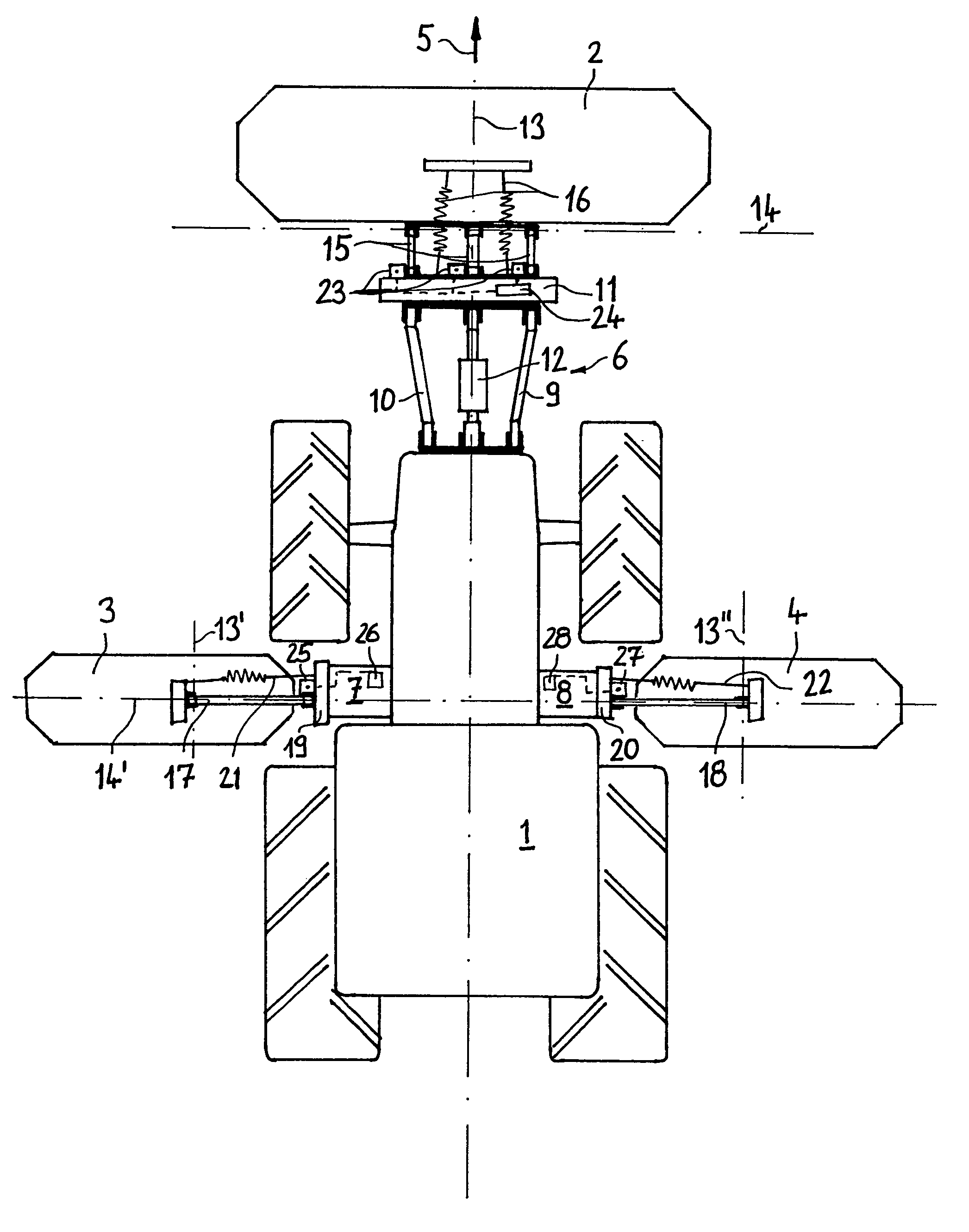
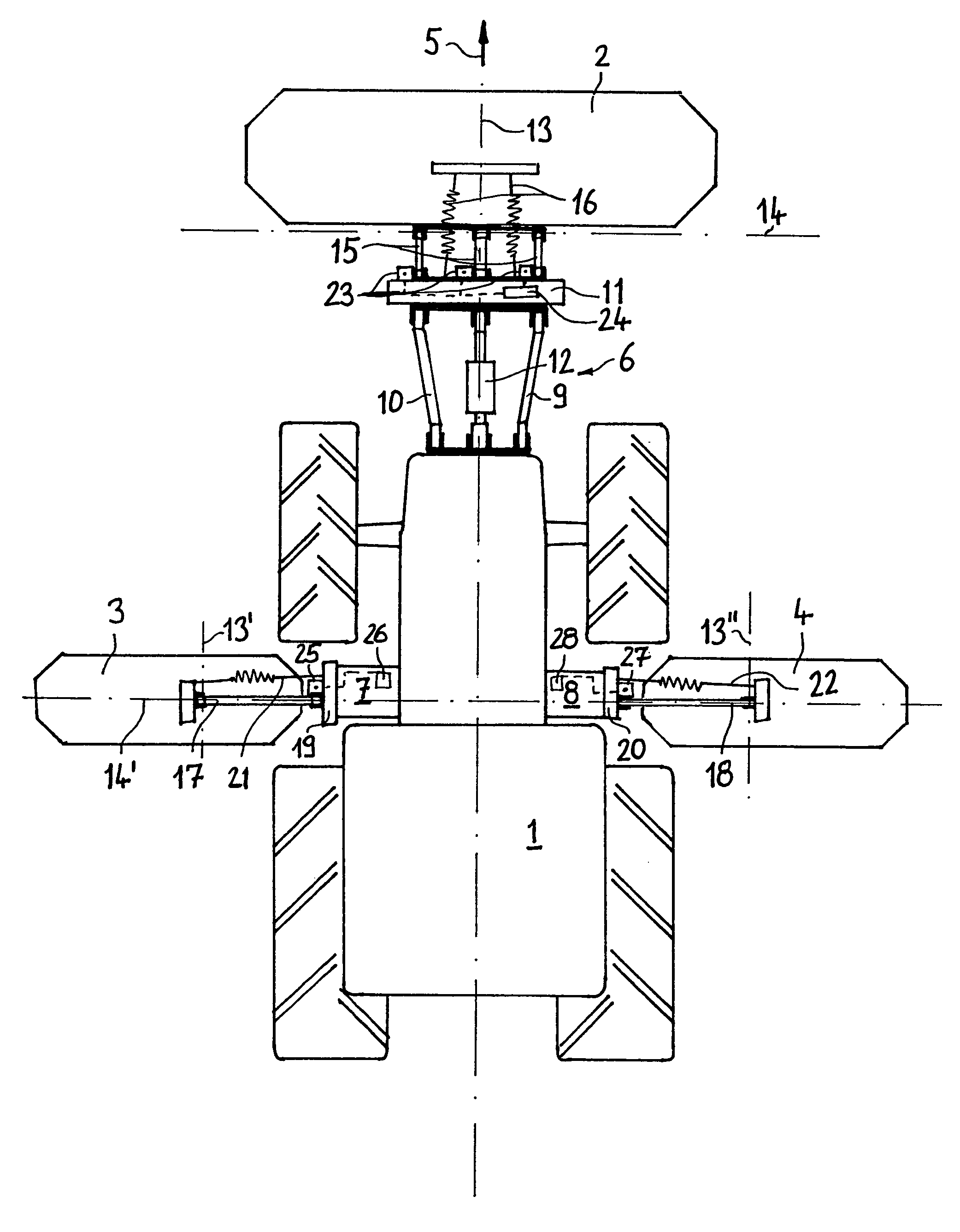
[0024]The figures show an implement carrier vehicle in the form of an agricultural tractor 1, driven in a working direction 5. A first mountable implement 2, a second mountable implement 3 as well as a third mountable implement 4 are connected to the tractor. The mountable implements 2, 3, 4 are arranged at a predetermined height above the ground and follow the height path of the ground. The mountable implements 2, 3, 4 can be represented by mowers, which rest on the ground and are slidingly moved along the ground.
[0025]The first mountable implement 2 is connected to the front side of the tractor 1 by a first attachment device 6. The second mountable implement 3 is connected via a second attachment device 7 and the third mountable implement 4 is connected via a third attachment device 8 to the tractor 1, respectively.
[0026]The first attachment device 6 is represented in the form of a three-point coupling (hitch) having two lower links 9, 10 as well as an upper link 12. The lower lin...
PUM
Abstract
A device for controlling the position of a mountable implement relative to an implement carrier vehicle has a mountable implement (2, 3, 4) which can be moved at a predetermined height by the implement carrier 1 following the ground. A support element (11, 19, 20), is coupled to the mountable implement (2, 3, 4) and can be attached to the implement carrier vehicle (1). A coupling device (15, 17, 18), is connected to the mountable implement (2, 3, 4) and to the support element (11, 19, 20). The mountable implement (2, 3, 4) is freely adjusted to a lifting position corresponding to the height path relative to the support element (11, 19, 20). An attachment device (6, 7, 8) attaches the support element (11, 19, 20) to the implement carrier vehicle 1 having a lifting device. A sensor determines the actual lifting position of the mountable implement (2, 3, 4) relative to the support element (11, 19, 20). A control device determines the deviation of the actual lifting position from a desired lifting position. The lifting device adjusts the support element (11, 19, 20) to a height position where the mountable implement (2, 3, 4) takes up the desired lifting position.
Description
CROSS-REFERENCE TO RELATED APPLICATIONS[0001]This application claims priority to German Patent Application No. 10247273.4 filed Oct. 10, 2002 which application is herein expressly incorporated by reference.FIELD OF THE INVENTION[0002]The invention relates to a device for controlling the position of a mountable implement relative to an implement carrier vehicle, especially a tractor. The control of the position of the mountable implement is necessary to follow the contour of the ground. The mountable implement, when it is moved by a tractor along the ground with an uneven ground contour, should be prevented from lifting off the ground or being pressed, with an abutment force which is too large, into the ground.BACKGROUND OF THE INVENTION[0003]Known systems which follow the ground contour include, for example, a carrier frame attached to a three-point coupling of a tractor. The carrier frame takes up a working device, for example, a mower where the mower is connected, via several link...
Claims
Application Information
Patent Timeline
Application Date:The date an application was filed.
Publication Date:The date a patent or application was officially published.
First Publication Date:The earliest publication date of a patent with the same application number.
Issue Date:Publication date of the patent grant document.
PCT Entry Date:The Entry date of PCT National Phase.
Estimated Expiry Date:The statutory expiry date of a patent right according to the Patent Law, and it is the longest term of protection that the patent right can achieve without the termination of the patent right due to other reasons(Term extension factor has been taken into account ).
Invalid Date:Actual expiry date is based on effective date or publication date of legal transaction data of invalid patent.