
Electric power tool

a technology of electric power tools and power tools, which is applied in the direction of portable power tools, manufacturing tools, drilling machines, etc., can solve the problems of limiting the service life of transmissions, increasing the cost and size of power tools, and large cooling requirements of transmissions, so as to reduce costs, reduce costs, and reduce the effect of reducing the siz

Active Publication Date: 2005-12-06
MATSUSHITA ELECTRIC WORKS LTD
View PDF9 Cites 50 Cited by
  • Summary
  • Abstract
  • Description
  • Claims
  • Application Information

AI Technical Summary

Benefits of technology

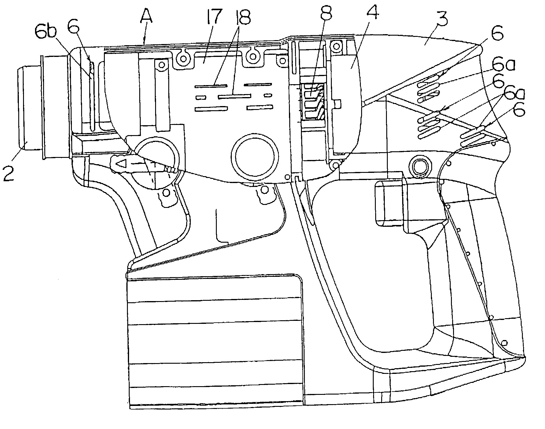
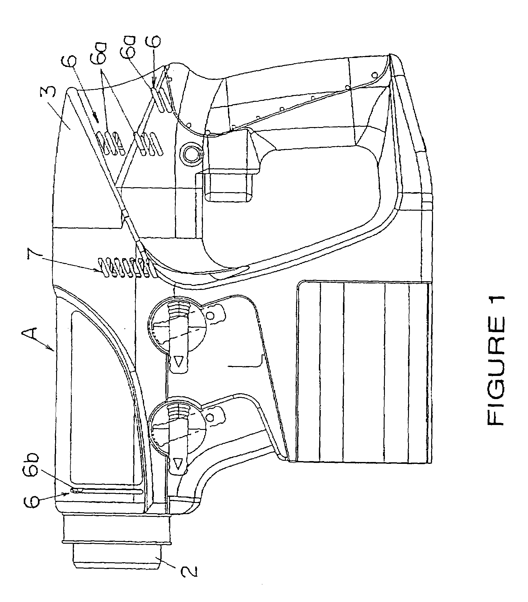
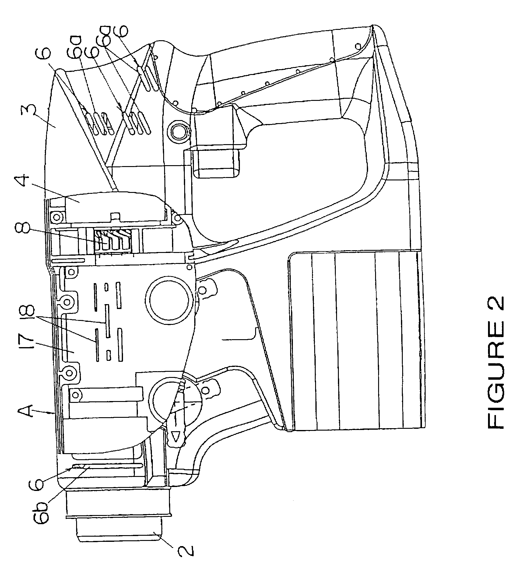
[0010]Considering the shortcomings of the prior art construction, the present invention provides an electric power tool incorporating a simplified cooling mechanism through which the motor and transmission can be efficiently cooled by a fan that allows the power tool to be made at reduced cost and to more compact dimensions.

Problems solved by technology

This type of cooling system, however, is not able to sufficiently cool the transmission whose gears rotate at high RPM and generate a large amount of thermal energy, thus limiting the service life of the transmission.
Moreover, the structure shown in FIG. 15 exhibits a shortcoming in that the use of motor cooling fan 19 and transmission cooling fan 22 results in a more complex structure that increases both the cost and the size of the power tool.
If this type of fan were constructed to deliver a volume of cooling air sufficient to cool the motor, which produces a greater amount of thermal energy than the transmission, the fan would be too large for the cooling requirements of the transmission, and thus put an unnecessary load on the motor.

Method used


Image

  • Electric power tool
  • Electric power tool
  • Electric power tool

Examples


second embodiment

[0064]In this second embodiment, blades 11 are provided on one side of base plate 9, and fan blades 14 are provided on the other. If the number of blades 11 on the motor side of base plate 9 is greater than the number of blades 14 on the transmission side, fan 8 will draw in a volume of intake air that is larger on the motor side of the fan than on the transmission side. The flow volume generated by blades 11 and 14 can thus be established at levels that provide sufficient streams of cooling air in respect to the thermal energy generated by the motor and transmission.

third embodiment

[0065]FIGS. 13a, 13b, and 13c illustrate the electric power tool invention. The following description will omit reference to identically numbered components in the other embodiments.

[0066]In this third embodiment, height H1 of blades 11 differ from height H2 of blades 14 to differentiate the volume of air drawn in by each group of blades. That is, by establishing H1 of blades 11 to a height greater than H2 of blades 14, a larger volume of air can be drawn in from the motor side of the power tool than from the transmission side, thereby providing for two separate streams of cooling air in different volumes appropriate to their respective applications.

[0067]In the embodiments presented in FIGS. 11 through 13, cylindrical boss 16 is provided to allow the attachment of fan 8 to shaft 15 of motor 4. Cylindrical boss 16 has an external diameter that becomes smaller at points increasingly farther from base plate 9 to smooth the air flow into fan 8, increase intake air flow efficiency, and ...


PUM

PropertyMeasurementUnit
transmit poweraaaaaaaaaa
volumeaaaaaaaaaa
transmissionaaaaaaaaaa

Abstract

An electric power tool incorporating a single fan that provides efficient cooling of the motor and transmission while reducing the cost and size of the power tool. The power tool includes a speed reduction transmission provided within a housing between the motor and a chuck which is located at the front end of the power tool. The rotation of the fan cools the motor and the transmission by drawing in external air from intake ports formed in the housing, and collectively exhausts the warmed cooling air through exhaust ports formed in the housing. The power tool includes a fan, located between the motor and the transmission, that is constructed to draw in two separate streams of cooling air from air intake ports located adjacent to the motor and the transmission, and to exhaust used cooling air through exhaust ports located adjacent to the fan.

Description

BACKGROUND OF THE INVENTION[0001]1. Field of the Invention[0002]The invention relates to an electric power tool, and more particularly to an electric power tool equipped with a highly efficient cooling fan to remove thermal energy generated by an electric motor and transmission.[0003]2. Description of Related Art[0004]Electric power tools generally employ a cooling system including a cooling fan attached to the motor output shaft whereby the rotation of the motor spins the cooling fan to draw cooling air to the motor from an upstream intake air duct in the housing, and away from the motor through a downstream exhaust air duct. This type of cooling system, however, is not able to sufficiently cool the transmission whose gears rotate at high RPM and generate a large amount of thermal energy, thus limiting the service life of the transmission.[0005]In an attempt to resolve this problem, an electric power tool of the type disclosed in Japanese Kokai Patent H9-11158 and shown here in FIG...

Claims


Application Information

Patent Timeline
Patent Type & Authority Patents(United States)
IPC IPC(8): B25F5/00H02K7/116H02K7/14H02K9/06
CPCB25F5/008H02K7/116H02K7/145H02K9/06
Inventor YAMADA, YUTAKAIWANO, HIROSHI
Owner MATSUSHITA ELECTRIC WORKS LTD
Learn More