Stabilizing system and methods for a drill bit

a technology of stabilizing system and drill bit, which is applied in the direction of drilling rods, drilling pipes, cutting machines, etc., can solve the problems that the drill bit cannot be properly stabilized by the stabilizing members, and achieve the effect of facilitating the reduction of the surface area

Inactive Publication Date: 2005-12-06
RANEY RICHARD C
View PDF37 Cites 60 Cited by
  • Summary
  • Abstract
  • Description
  • Claims
  • Application Information

AI Technical Summary

Benefits of technology

[0005]The structure of the present invention may be generally similar to that shown in prior U.S. Pat. No. 4,842,083; except that the various improvements have been provided, both as to the methods and stabilizing system of the invention. In one aspect, the invention is directed to a drill bit stabilizing system comprising a body member having an axis, and at least one recess formed in the body member for housing at least one stabilizing member when in a first retracted position. The at least one stabilizing member is biased to a second extended operating position. The body member further comprises at least one fixed stabilizing surface positioned in axially spaced relationship to the at least one movable stabilizing member. In another aspect, the invention is directed to a drill bit stabilizing system comprising a body member and at least one stabilizing member, being moveable from an extended operating position to a retracted position within the body member. The at least one stabilizing member comprises outer contact faces adapted to engage the wall of a bore hole when in an operating position, and an inner slide surface adapted to slidingly engage a corresponding slide surface formed in the body member. The inner slide surface comprises at least one relief groove to facilitate the reduction of the surface area of the surface and thereby provide a predetermined increase in the contact pressure per square inch between the inner slide surface and corresponding slide surface associated with the body member. In a further aspect, the slideable, wedge shaped stabilizing m

Problems solved by technology

It has also been found that under certain conditions, the bit may not be properly stabilized by the stabilizi

Method used


Image

  • Stabilizing system and methods for a drill bit
  • Stabilizing system and methods for a drill bit
  • Stabilizing system and methods for a drill bit

Examples


Embodiment Construction

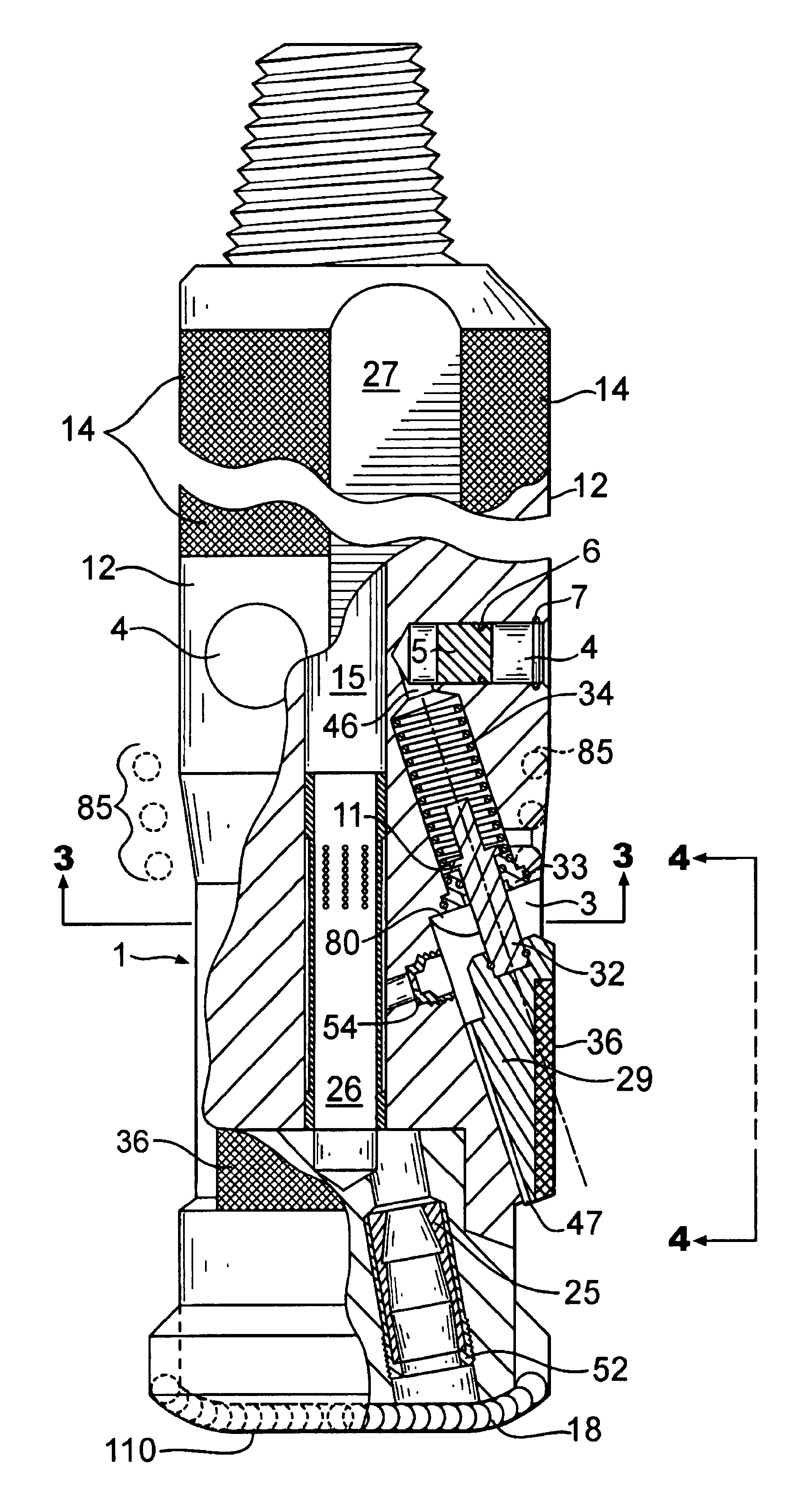
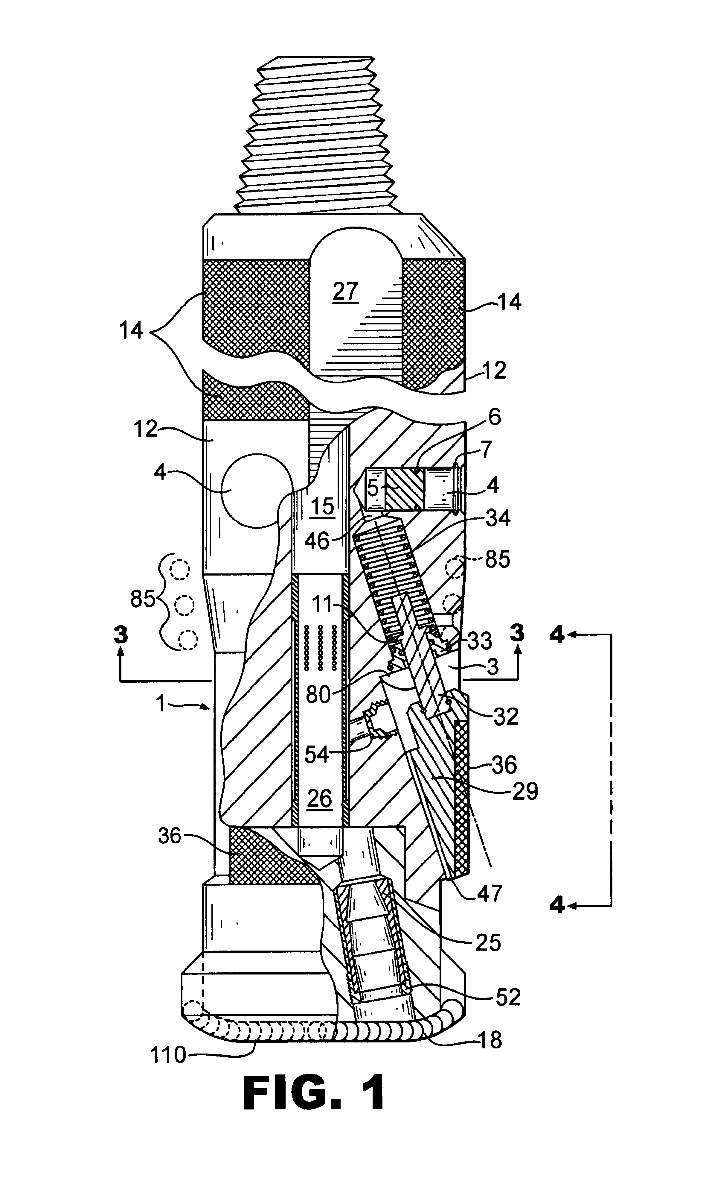
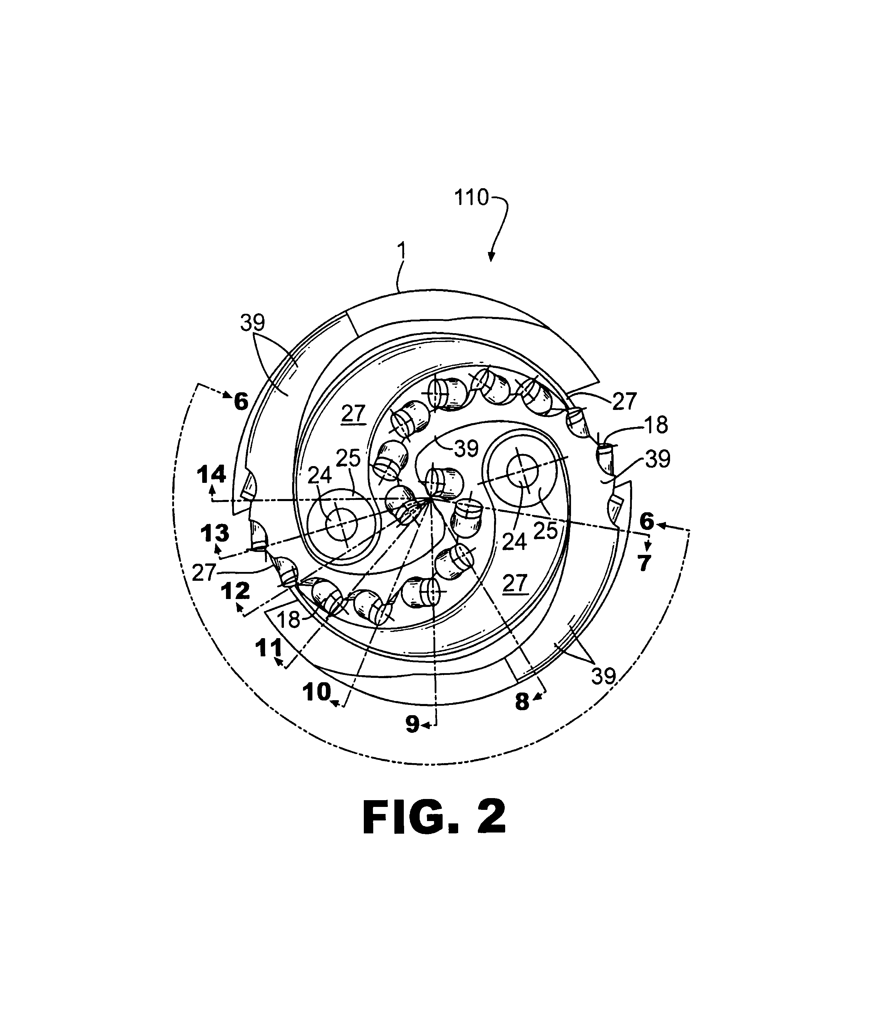
[0016]Referring to the figures of the drawings, the embodiment comprises an improved stabilizer and drill bit, generally indicated by the numeral 100. The invention in one aspect is generally directed to a drill bit stabilizer having a main body of generally cylindrical configuration and a pin end opposed to a lower drilling end. The system is attachable to or includes a drill bit for making a borehole when rotation occurs. A throat is formed longitudinally through the main body of the stabilizer for passage of drilling fluid from a drill string, through the body, and through nozzles of the bit. The drilling fluid exits the bit and returns up the borehole annulus. A plurality of circumferentially arranged wedge shaped pockets or recesses are formed about the main body from the outer surface of the main body inward to slideably receive corresponding wedge shaped stabilizing members. Means are provided by which the stabilizing members are spring actuated. The stabilizing members are e...


PUM


Abstract

A drill bit stabilizing system comprising a body member having an axis and at least one recess formed in the body member housing at least one stabilizing member when in a first retracted position. The stabilizing member is positionable along a diagonal angle with the axis to a second extended operating position which extends downward and outward relative to the main body to selectively engage the surface of a pilot bore hole wall during a drilling operation so as to stabilize an under gauge drill bit used in association with the stabilizing system. The body member further comprises at least one fixed stabilizing surface positioned in an axially spaced relationship to the at least one movable stabilizing member. The body member further comprises a gauge cutter positioned above the moveable stabilizing member and below the fixed stabilizing surface to expand the pilot hole to the final gauge.

Description

TECHNICAL FIELD[0001]This invention relates generally to drill bit and drill bit stabilizing systems and methods for use in borehole forming operations wherein a drill bit is connected to a drill string and rotated while drilling fluid flows down the drill string to the drill bit for circulating cuttings up the borehole as the hole is drilled. More particularly, the invention relates to stabilizing systems and methods for stabilization of a drill bit so as to minimize vibration and possible damage to the drill bit or other structures.BACKGROUND OF THE INVENTION[0002]My prior U.S. Pat. Nos. 4,842,083; 4,856,601; and 4,690,229, which are hereby incorporated by reference, are directed to drilling systems and methods providing distinct advantages. U.S. Pat. No. 4,842,083, entitled “Drill Bit Stabilizer”, is directed to a stabilizing system to stabilize the drill bit and drilling string in a down hole system, and the present invention is directed to improvements in the system and methods...

Claims


Application Information

Patent Timeline
IPC IPC(8): E21B10/42E21B10/43E21B10/60E21B10/62E21B17/10
CPCE21B10/43E21B10/60E21B10/62E21B17/1014
Inventor RANEY, RICHARD C.
Owner RANEY RICHARD C
Why Eureka
Try Eureka