
Onboard fuel separation apparatus for an automobile

a fuel separation and automobile technology, applied in the direction of hydrocarbon purification/separation, combustion air/fuel air treatment, machines/engines, etc., can solve the problems of difficult to achieve a large increase in ron of a high octane product, and the membrane type used is not selectiv

Inactive Publication Date: 2005-12-06
EXXON RES & ENG CO +1
View PDF6 Cites 104 Cited by
  • Summary
  • Abstract
  • Description
  • Claims
  • Application Information

AI Technical Summary

Benefits of technology

[0012]The object as set forth above is achieved by an onboard fuel separation apparatus for an automobile comprising a separation membrane for separating a fuel supplied as an input material into a high-octane fuel containing a larger amount of high octane value components than the material fuel and a low-octane fuel containing a larger amount of low octane value components than the material fuel by selectively allowing high-octane value components in the material fuel to permeate therethrough and forming a high-octane fuel on one side thereof and a low-octane fuel on the other side thereof and octane value increasing means which, when activated, increases the amount of high-octane value components contained in the high-octane fuel separated by the separation membrane compared with the case where the octane value increasing means is not activated.
[0013]According to the present invention, when the octane value increasing means is activated, the amount of the high-octane value components contained in the high-octane fuel increases. Therefore, the octane value of the high-octane fuel becomes higher and the difference between the octane values of the high-octane fuel and the low-octane fuel becomes larger when the octane value increasing means is activated.

Problems solved by technology

However, the type of membrane employed is not selective to compound types; i.e., aromatics versus linear paraffins.
As explained above, it is difficult to achieve a large increase in RON of a high octane product relative to the original fuel in the apparatus in the '115 or in the SAE 2001-01-1193 publications.

Method used


Image

  • Onboard fuel separation apparatus for an automobile
  • Onboard fuel separation apparatus for an automobile
  • Onboard fuel separation apparatus for an automobile

Examples


Embodiment Construction

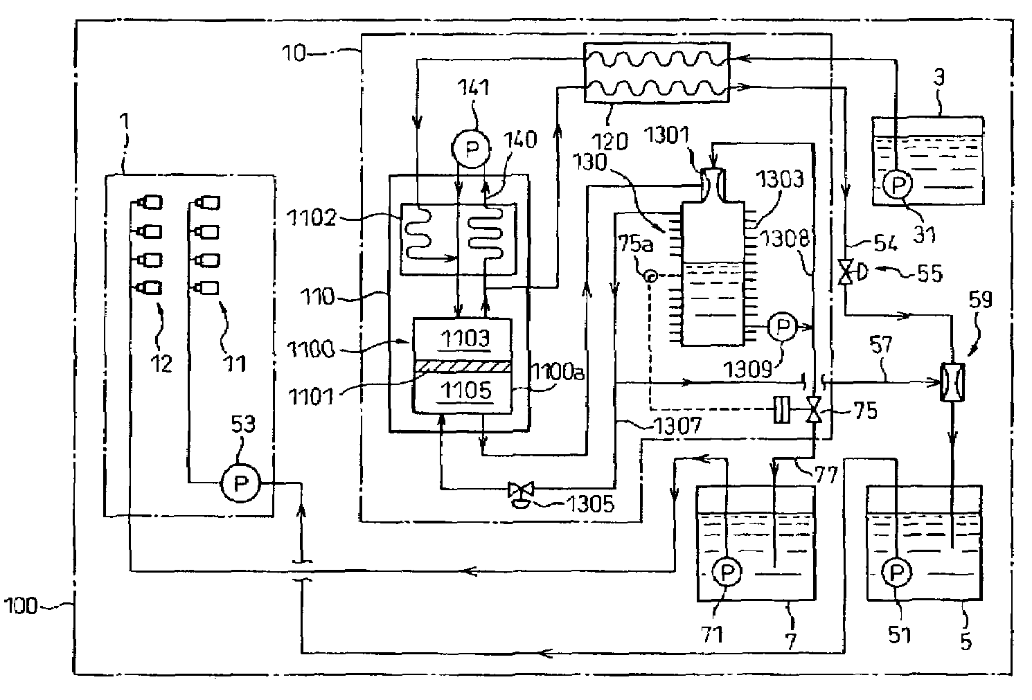
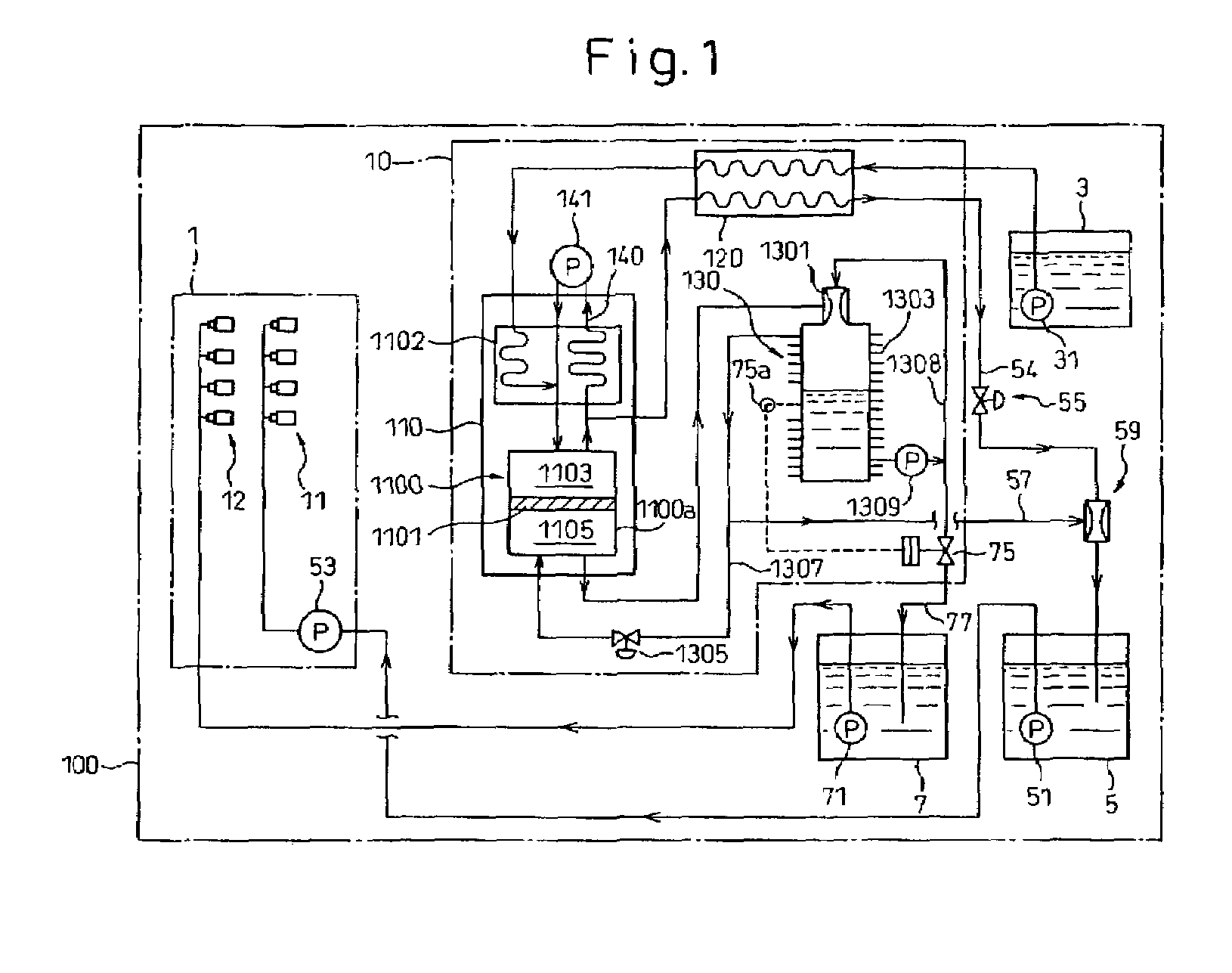
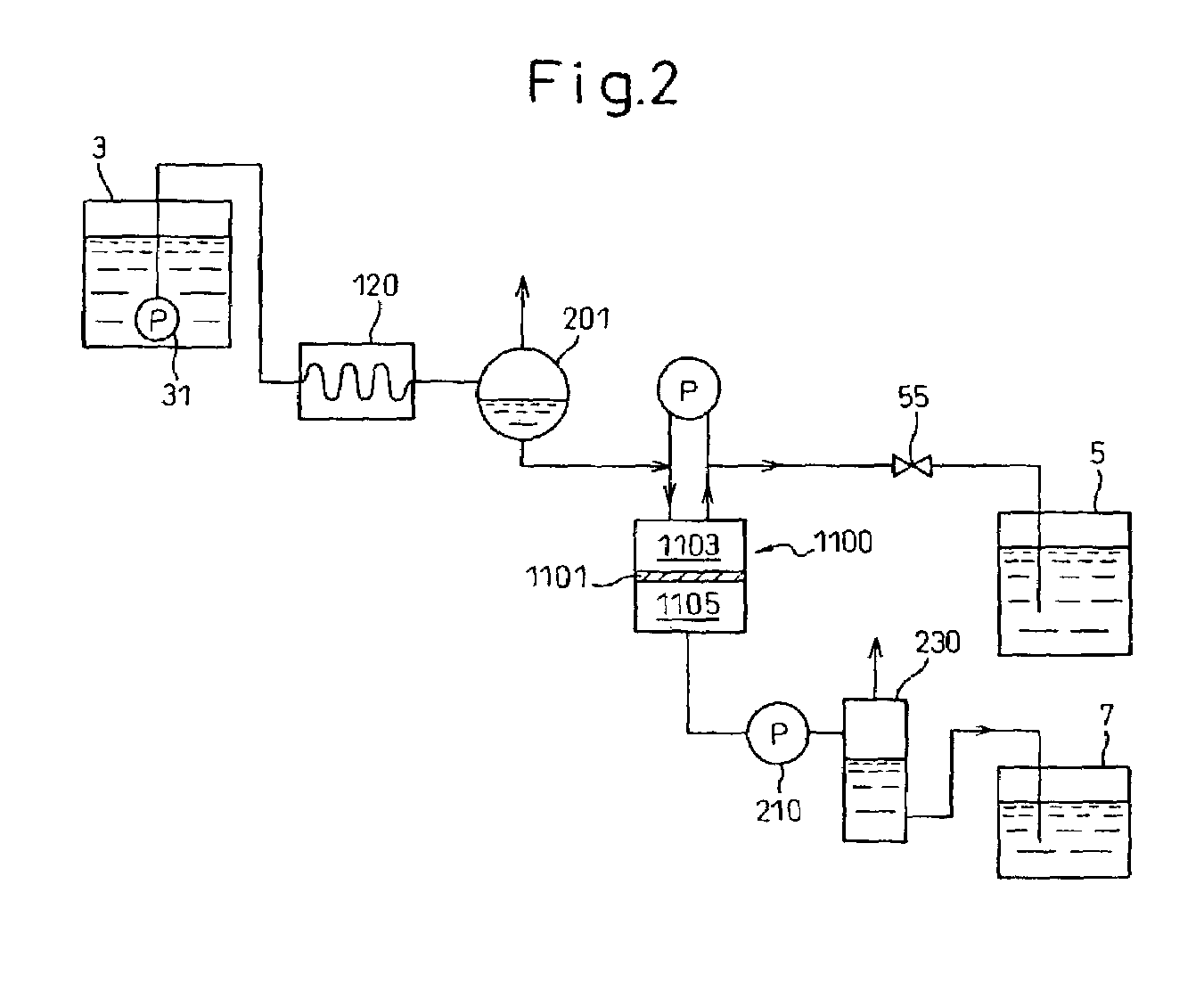
[0018]Hereinafter, embodiments of the onboard fuel separation apparatus for automobile according to the present invention will be explained with reference to FIGS. 1 and 2.

[0019]FIG. 1 schematically shows the construction of an embodiment of the onboard fuel separation apparatus according to the present invention.

[0020]In FIG. 1, reference numeral 1 designates an automobile internal combustion engine, 11 and 12 collectively designates fuel injection valves of the engine 1. In this embodiment, as explained later, a high-octane fuel having a higher octane value and a low-octane fuel having a lower octane value are used for the engine 1 and two separate fuel injection valves 11 and 12 are disposed on each cylinder of the engine 1 in order to supply the high-octane fuel and low-octane fuel separately to the engine cylinder.

[0021]In this embodiment, direct cylinder fuel injection valves are used for the low-octane fuel injection valve 11 for injecting the low-octane fuel directly into th...


PUM

PropertyMeasurementUnit
Angleaaaaaaaaaa
Temperatureaaaaaaaaaa
Partial pressureaaaaaaaaaa

Abstract

An onboard fuel separation apparatus separates a material fuel (gasoline) into a high-octane fuel having a higher octane value than the material fuel and a low-octane fuel having a lower octane value than the material fuel using a separation membrane which selectively allows high-octane value components (such as aromatic components) permeate through the membrane. The apparatus increases the ratio of the amount of the high-octane value components permeating through the membrane to the amount of the high-octane value components contained in the material fuel by, (A) Controlling the temperature of the material fuel supplied to the membrane (B) Increasing partial pressure of the low-octane value components on the high-octane fuel side of the membrane and removing volatiles from the permeate, and (C) Bypassing volatiles in the material feed around the membrane.

Description

BACKGROUND OF THE INVENTION[0001]1. Field of the Invention[0002]The invention relates to an onboard fuel separation apparatus for an automobile and, more specifically, to an onboard fuel separation apparatus having a separation membrane that separates a material fuel into a high-octane fuel and a low-octane fuel.[0003]2. Description of Related Art[0004]A fuel separation apparatus using a separation membrane which is capable of separating a fuel supplied to the apparatus (i.e., a fuel used as a material) into fuels having different properties is known in the art.[0005]A fuel separation apparatus of this type is, for example, disclosed in the Japanese Unexamined Patent Publication (Kokai) No. 5-312115. An apparatus of the '115 publication separates gasoline in a gasoline tank into a fuel having a high-boiling point and a fuel having a low-boiling point, by using a pervaporation membrane, and stores the obtained low boiling point fuel in a fuel tank. At the time of a startup or a cold ...

Claims


Application Information

Patent Timeline
IPC IPC(8): F02M33/00C10G31/11F02D19/06F02D33/00F02M25/00F02M37/00
CPCC10G31/11F02D33/006F02M25/00F02M37/0064F02M37/0088F02M69/046F02D19/0649F02D19/0665F02D19/0671F02M43/00Y02T10/36Y02T10/30
Inventor PARTRIDGE, RANDALL D.WEISSMAN, WALTERUEDA, TAKANORIIWASHITA, YOSHIHIRO
Owner EXXON RES & ENG CO
Learn More