User interface and a synthesizer with a user interface

Inactive Publication Date: 2005-12-06
APPLE INC
View PDF6 Cites 12 Cited by
  • Summary
  • Abstract
  • Description
  • Claims
  • Application Information

AI Technical Summary

Benefits of technology

[0005]The present invention is thus directed towards a user interface for facilitati

Problems solved by technology

The complexity of such synthesizers has developed enormously over the last decade.
This enhances the complexit

Method used


Image

  • User interface and a synthesizer with a user interface
  • User interface and a synthesizer with a user interface
  • User interface and a synthesizer with a user interface

Examples


first embodiment

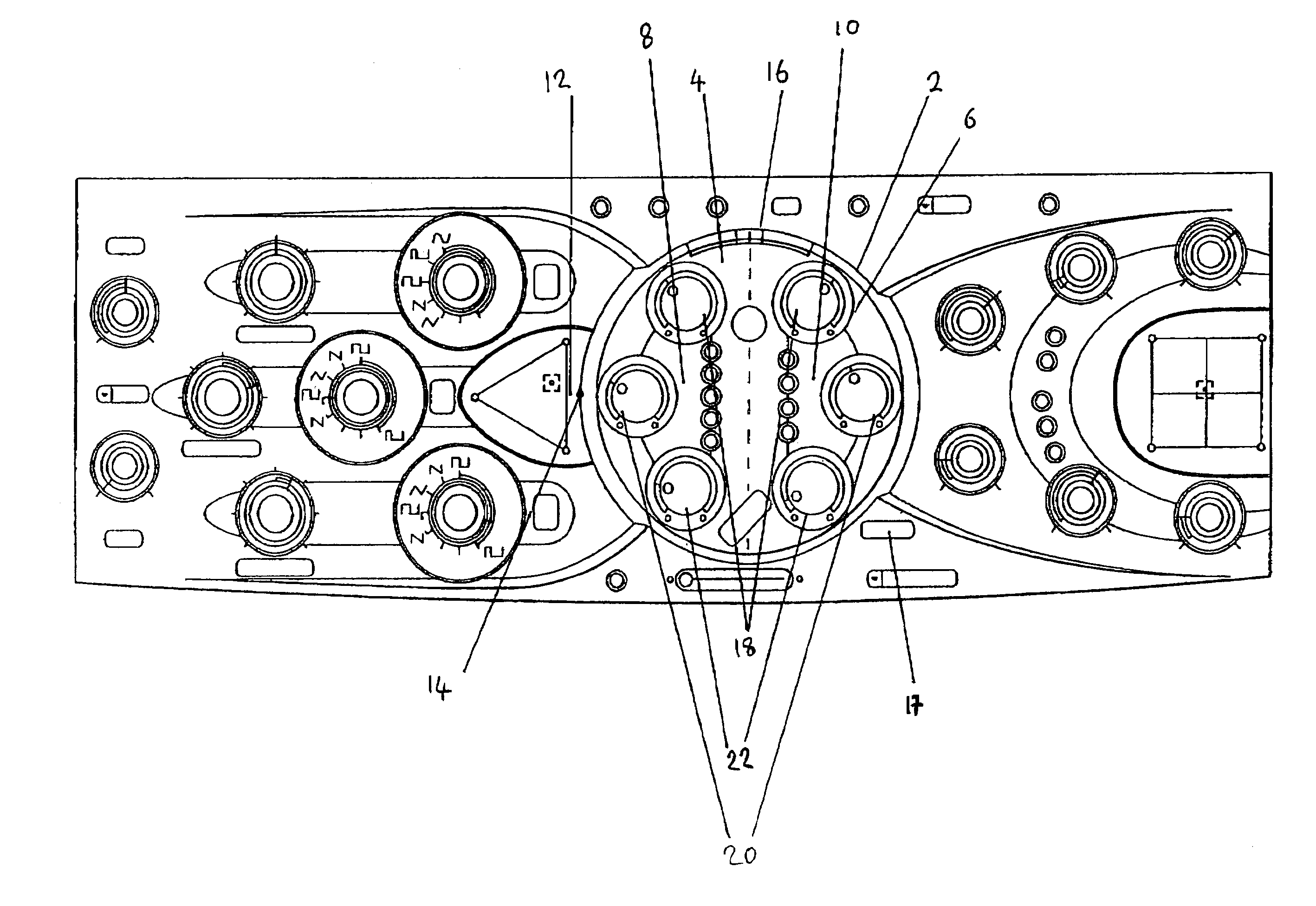
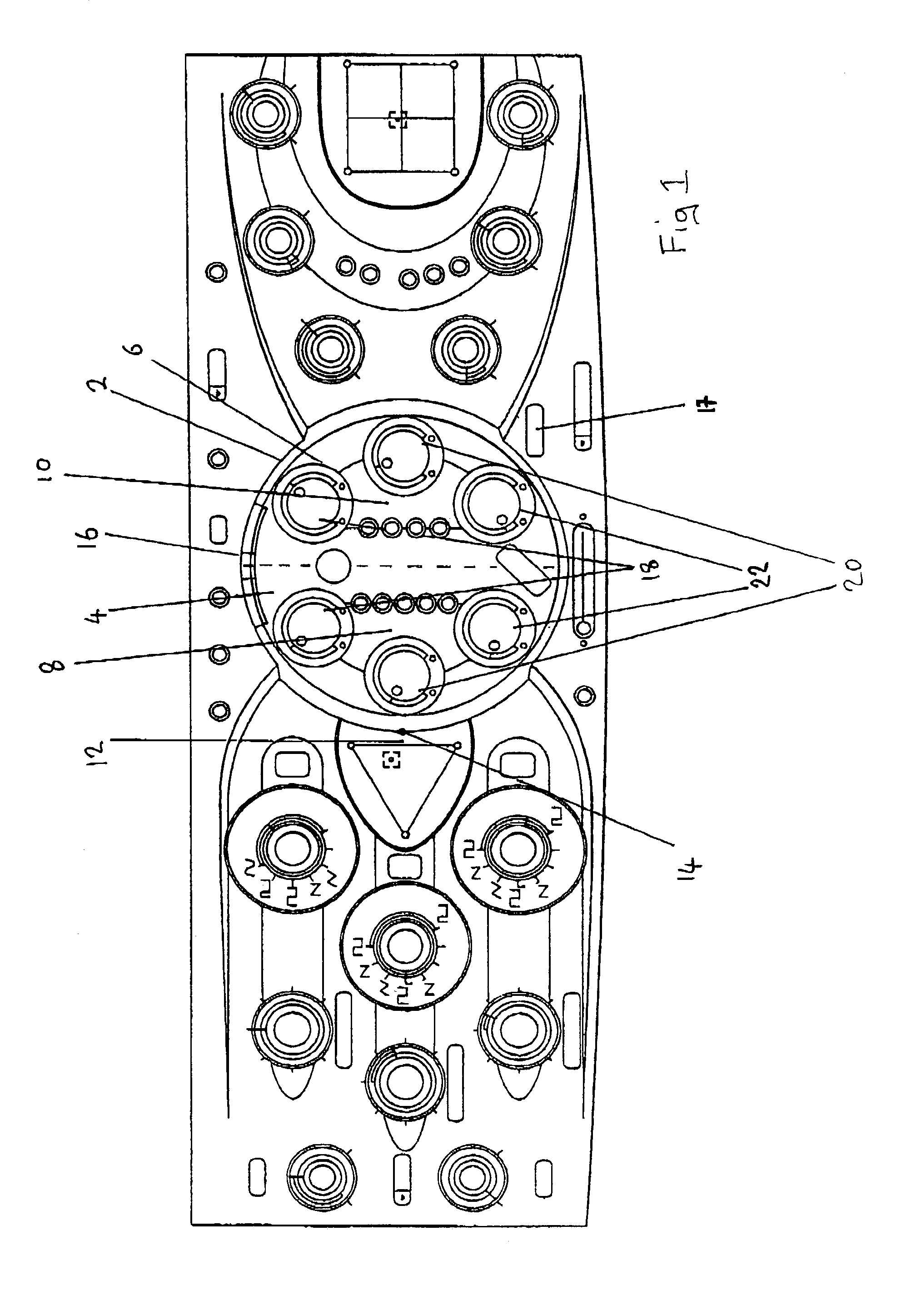
[0012]In FIG. 1 there is shown a user interface according to the present invention. The user interface comprises a rotatable controller 2. The rotatable controller 2 may be part of a synthesizer for creating and / or editing sounds (e.g. music). The controller is defined by two sectors 4 and 6, each having a 90° arc. Each sector 4, 6 relates to a filter 8, 10.

[0013]A signal input 12 is represented as being input at position 14 with respect to the rotatable controller 2. Position 14 is located at 270° degrees with respect to the user interface.

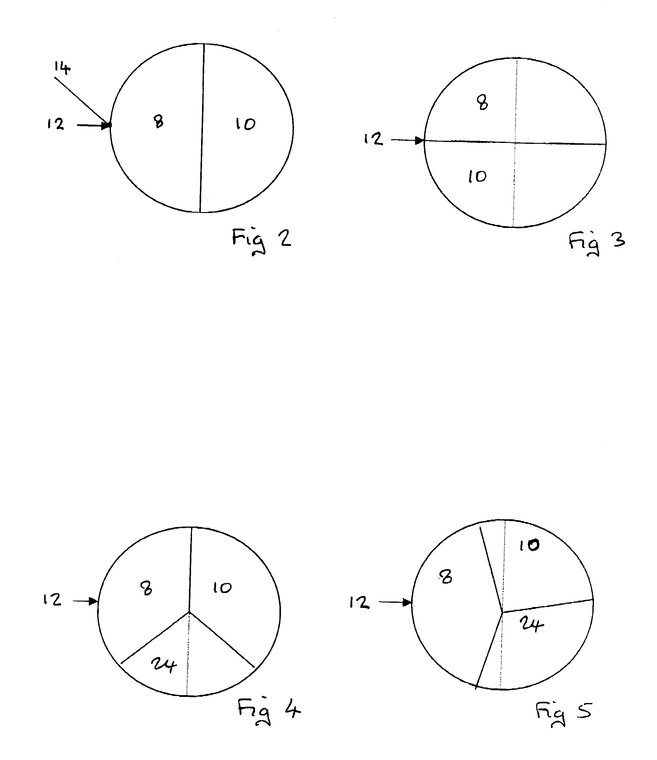
[0014]In operation, a user, when using the user interface, rotates the rotatable controller 2 to vary the application of filters 8 and 10. FIG. 2 is a schematic illustration of the first embodiment when the filters are aligned with the 0° and 180° positions with respect to the user interface and so apply the filters in series. That is to say, the input signal is fed into filter section 8 and the output of which is passed to filter section 10. FIG...

second embodiment

[0019]The rotatable controller 2 may comprise not just two filters but any number of filters. FIGS. 4 and 5 schematically illustrate a rotatable controller with three filters in accordance with the In FIG. 4, filters 8, 10 and 24 each command a sector of 120°. Filters 8 and 10 are aligned with 0° and filter 24 with 60° and 210°. Thus, in FIG. 4, filters 8 and 10 are applied in series to the input signal with filter 24 being applied also in series either in between filters 8 and 10 or after filter 10.

[0020]FIG. 5 illustrates the rotatable control means whereby filters 8, 10 and 24 are each applied in parallel to each other. Alternatively, filter 8 is applied to the input signal and the output of which is fed to filters 10 and 24 being applied in parallel to each other.

[0021]A switch such as shown at 17 in FIG. 1 can be used to select among the variations when there are three or more filters.

[0022]The user interface of the present invention provides a control for the filtering which ...


PUM


Abstract

A synthesiser to generate sounds often in a musical environment but also in a speech environment. Such synthesis of sounds is often accompanied by at least one mode of filtering or many modes. Hitherto, the application of such filtering has involved a control for each filter. This may be by way of a lever, toggle or rotatable knob. Thus, a user when applying the filters is required to adjust each control independently of the other. This enhances the complexity and a large amount of skill is involved in accurately selecting the required amount and types of filtering.
Thus, the present invention is directed towards a user interface for controlling the filtering of a signal input (such as a sound), said user interface comprising a rotatable controller having two or more sectors, each sector of said controller corresponding to a respective filter, whereby in use said controller is rotated to align said sectors with respect to said signal input thereby controlling the application of the filters to the signal input.

Description

FIELD OF THE INVENTION[0001]The present invention relates to a user interface and to a synthesizer and in particular but not exclusively to a user interface in a synthesizer.BACKGROUND OF THE INVENTION[0002]A synthesizer is provided to generate sounds often in a musical environment but also in a speech environment. The complexity of such synthesizers has developed enormously over the last decade. None the less, such synthesis of sounds is often accompanied by at least one mode of filtering or many modes. These modes may include any one of low-pass filtering, high-pass filtering, band-pass filtering, notch filtering, peak filtering or comb filtering as well as discrete filtering for each octave. Moreover, when there are more than two filters, they may be applied in series or in parallel.[0003]Hitherto, the application of such filtering has involved a control for each filter. This may be by way of a lever, toggle or rotatable knob. Thus, a user when applying the filters is required to...

Claims


Application Information

Patent Timeline
IPC IPC(8): G10H1/12
CPCG10H1/12
Inventor DIEDRICHSEN, STEFFAN
Owner APPLE INC
Why Eureka
Try Eureka