System, method and apparatus for MRI maintenance and support

a technology of magnetic resonance imaging and maintenance logs, applied in the direction of local control/monitoring, using reradiation, instruments, etc., can solve the problems of difficult to determine when or where the degradation of the malfunctioning part started, difficult to access the service logs and provide service quickly and efficiently, etc., to achieve the effect of preventing or quickly recovering faults

Inactive Publication Date: 2005-12-06
TOSHIBA MEDICAL SYST CORP
View PDF8 Cites 26 Cited by
  • Summary
  • Abstract
  • Description
  • Claims
  • Application Information

AI Technical Summary

Benefits of technology

[0021]It is an object of the present invention to minimize the time associated with an investigation to determine the condition of the apparatus as much as possible, accelerate the dispatch of repair units, and repair the apparatus swiftly. Additionally, it is preferable to determine whether the trouble occurred suddenly or gradually according to the service log, and to make this determination accurately. Moreover it is preferable to anticipate long-term or middle-term troubles at an early stage by recognizing degradation of the apparatus according to results of diagnostic checks, and to prevent future system failures.
[0026]Therefore, both automatically measured data and manually input data can be obtained swiftly and faults can be recovered quickly or prevented in advance.

Problems solved by technology

However, because the results of such checks or routine maintenance are not stored in the MRI apparatus, and are retained in separate locations, it is difficult to access these service logs and to provide service quickly and efficiently.
It is difficult to recognize and determine degradation of the MRI apparatus by merely viewing images obtained by the general imaging methods (SE, FSE, etc.), as compared with also viewing images obtained using specialized imaging techniques such as those mentioned above (FASE, EPI, etc.) which exercise a larger range of performance of the apparatus.
Therefore, even if an image actually indicates some degree of degradation, it is difficult to determine when or where the degradation of the malfunctioning part started.
There are also failure and degradation conditions of the apparatus which do not affect the quality of the image directly.
In that case, it is time consuming and labor intensive to determine whether the fault or degradation conditions occurred suddenly or gradually.
It is also difficult to gather related information.
Thus, the determination that they are out of order typically occurs in an untimely manner.
Since an MRI apparatus includes many different constituent units, it is difficult to confirm the part, start time and grade of malfunction when an imaging fault occurs under, for example, specific image conditions.
Therefore, achieving repair becomes time consuming and inefficient.
In addition, because all log data regarding each apparatus is not consolidated, it becomes particularly burdensome to statistically manage and upgrade the MRI apparatuses.
Under such conditions, for example, the following problems may occur.
(b) Since the serviceman repairs only according to the manual, it may take considerable time to confirm new troubles which are not described in the manual.
(c) It is difficult to compare the diagnostic check results of the apparatuses and analyze them to determine a trend of faults or malfunctions.
(d) Because it is difficult to confirm the upgrade record, the serviceman cannot serve the customer according to the conditions peculiar to each apparatus.
(e) If the conditions of the apparatus are such that there is the possibility of an accident or harm to a patient, no one may be alerted to the condition or notice the condition in a timely manner.
(f) It may take considerable time to exchange the units, because an order for exchange flows by way of the service provider.

Method used


Image

  • System, method and apparatus for MRI maintenance and support
  • System, method and apparatus for MRI maintenance and support
  • System, method and apparatus for MRI maintenance and support

Examples


Embodiment Construction

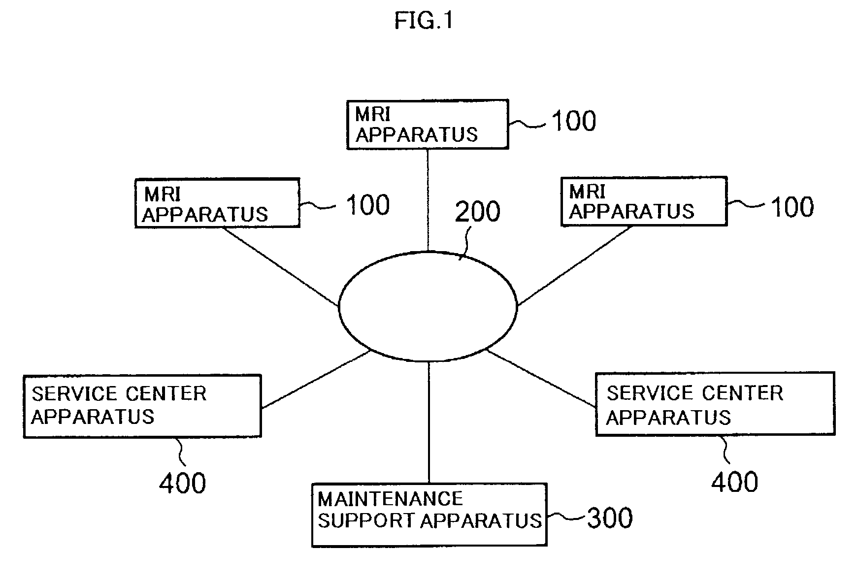
[0034]With reference to drawings, an exemplary embodiment of the invention will be described herein. FIG. 1 is a block diagram showing a maintenance support system. In this figure, a plurality of MRI apparatuses 100 are connected to a maintenance support apparatus 300 via a communication network 200, such as, for example, a general public line or a dedicated line. In addition, a plurality of service center apparatuses 400 are also connected to the maintenance support apparatus 300 via the communication network 200.

[0035]The maintenance support apparatus 300 stores data about each MRI apparatus 100. The data relates to all or at least one of adjustment, state of each part, repair, maintenance, check, software and hardware upgrade, software customizing, error, the conditions at the installation, the building construction and the network connection. The apparatus 300 sends information to the MRI apparatus 100 or the service center apparatus 400 as necessary. Thus the information stored...


PUM


Abstract

An MRI apparatus consolidates and stores maintenance and / or performance data automatically measured by a measurement unit and data manually input via an input device. The automatically measured data may include an adjustment value, a state value or an error record. The manually input data may include a software and / or hardware upgrade record, a customized situation record, a network connection record, a repair record, a check record, a maintenance record or an installation record, for example. Both types of data can be obtained swiftly and faults or malfunctions can be recovered from quickly or even prevented in advance. The stored data may be communicated among a plurality of MRI apparatuses, a service center apparatus and a maintenance support apparatus via a communications network.

Description

CROSS-REFERENCE TO RELATED APPLICATIONS[0001]This application claims priority under 35 U.S.C. §119 to Japanese patent application No. P2001-398391 filed Dec. 27, 2001, the entire content of which are incorporated by reference herein.BACKGROUND OF THE INVENTION[0002]The present invention relates to a system, method and apparatus for providing maintenance and support for a magnetic resonance imaging (MRI) apparatus. In particular, the present invention is directed to a method, system and apparatus for providing preventative maintenance for MRI apparatuses, for quickly and efficiently diagnosing faults in an MRI apparatus, and for efficiently repairing faulty MRI apparatuses.[0003]Typically, a service log related to an MRI apparatus, such as a repair log and / or a performance / maintenance check log, is stored separately by a service provider and a customer. This log is used for various kinds of investigations, such as, for example, to find a cause of a fault that occurs in the MRI appara...

Claims


Application Information

Patent Timeline
Patent Type & Authority Patents(United States)
IPC IPC(8): G06F19/00
CPCG06F19/3412G06F19/324G06F19/3418G16H10/60G16H30/20G16H40/40
Inventor YOKOI, MOTOHISAKASSAI, YOSHIMORI
Owner TOSHIBA MEDICAL SYST CORP
Why Eureka
Try Eureka