Projection display for a aircraft cockpit environment

a technology for aircraft cockpits and projection displays, which is applied in the direction of projection devices, television systems, instruments, etc., can solve the problems of difficult replacement of optical engines, difficult maintenance of projection displays, and drawbacks of prior art projection displays

Active Publication Date: 2005-12-06
ROCKWELL COLLINS INC
View PDF7 Cites 50 Cited by
  • Summary
  • Abstract
  • Description
  • Claims
  • Application Information

AI Technical Summary

Problems solved by technology

However, the projection displays of the prior art have drawbacks.
The result is difficult maintenance of the projection display and difficult replacement of the optical engine.
Anyone familiar with maintenance of electrical and mechanical systems is aware that complicated and inconveniently installed machinery is harder to repair correctly and therefore more prone to failure.
In another drawback, the prior art projection display is not sealed.
Because the cockpit environment is not completely clean, dust and dirt may float around and may be stirred up by ventilation or by flight maneuvers.
The dirt may work its way into the prior art projection display and cause degraded performance or even failure of the device.
In addition, the cockpit environment may contain moisture which can cause corrosion or condensation that interferes with the display.

Method used


Image

  • Projection display for a aircraft cockpit environment
  • Projection display for a aircraft cockpit environment
  • Projection display for a aircraft cockpit environment

Examples


Embodiment Construction

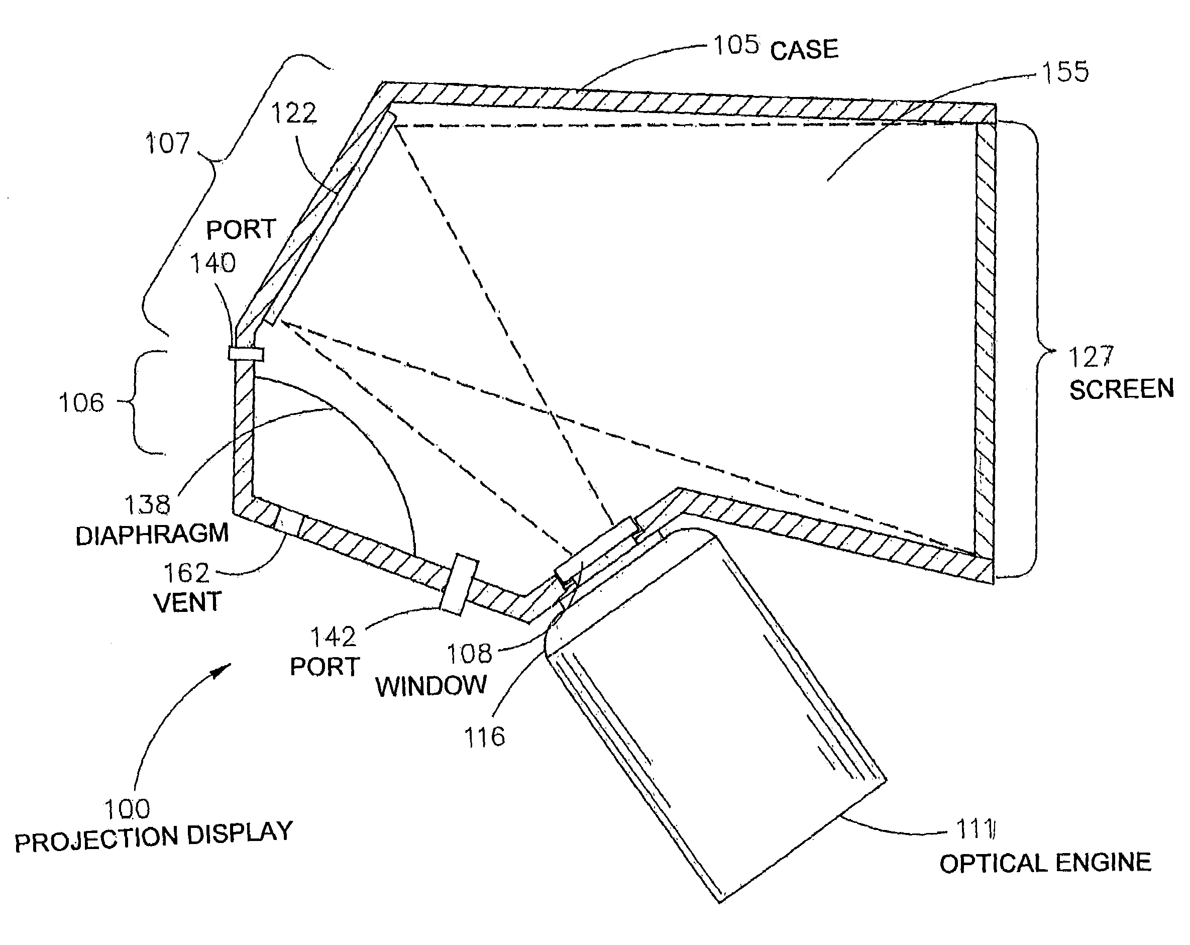
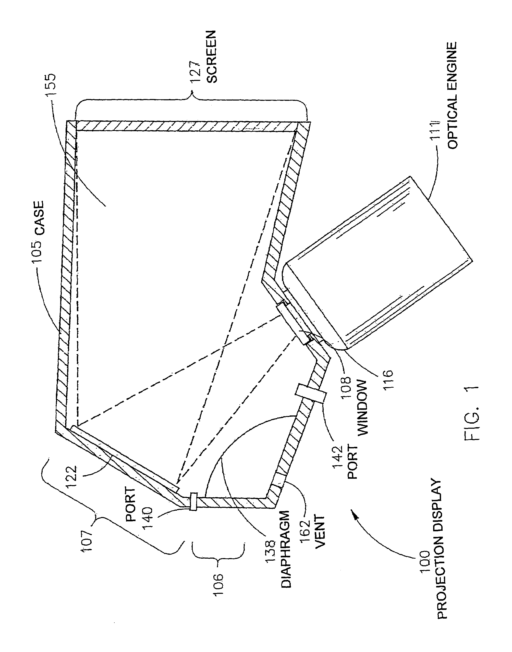
[0013]FIG. 1 shows a projection display 100 according to one embodiment of the invention. The projection display 100 includes a case 105, a window 108, an optical engine 111, a dust boot 116, at least one mirror 122, a screen 127, a seal 135, a diaphragm 138, two external ports 140 and 142, an inert gas mixture 155, and an optional vent opening 162.

[0014]The case 105 is hollow and when the projection display 100 is fully assembled the case 105 is capable of containing a gas or gas mixture at an appropriate overpressure condition. The case 105 may be formed of a strong, light, non-porous material such as: aluminum, titanium, composite material, etc. The overpressure can be as little as about 5 pounds per square inch (psi), but in addition, the case 105 may support overpressures due to altitude changes from sea level to very high altitudes. The case 105 includes the screen 127, which may be translucent and may be formed as one end wall of the case 105. At least one first surface mirro...


PUM


Abstract

A projection display is provided according to one embodiment of the invention. The projection display includes a hollow case including a window opening, a screen formed on one portion of the case, and at least one mirror internally mounted to the case at a position to reflect light from the window opening to the screen. The projection display further includes a window mounted in the window opening. The projection display further includes an optical engine mounted to the case. The optical engine is positioned over the window and oriented so that emitted light from the optical engine is directed onto the at least one mirror. The projection display further includes a diaphragm internally attached to the case and dividing an internal volume of the case into a first portion and a second portion. The projection display further includes a gas filling the second portion of the case at an overpressure and a vent communicating with the first portion of the case and communicating with an external environment. The vent at least partially equalizes the overpressure of the second portion with a pressure of the external environment.

Description

FIELD OF THE INVENTION[0001]The present invention relates generally to projection display devices, and more particularly to a projection display for an aircraft cockpit environment.BACKGROUND OF THE INVENTION[0002]Modern aircraft cockpit instrumentation includes many complex electronic systems, including avionics, navigation systems, communications, engine and system gauges, etc. They are visual instrument systems that the aircraft crew use in operating the aircraft. Therefore, proper operation of all cockpit instruments is of the greatest importance. In addition, the cockpit instrumentation must be highly reliable in order to provide safe, reliable, and economical air travel.[0003]Prior art aircraft cockpit instrumentation has used projection displays. A projection display includes an optical image engine that creates and projects an electronically created image onto a screen. The resultant image can be viewed by one or more of the crew. The projection display may include one or mo...

Claims


Application Information

Patent Timeline
Patent Type & Authority Patents(United States)
IPC IPC(8): G02B27/00G02B27/01H04N5/64H04N5/74H04N9/31
CPCG02B27/0006G02B27/01H04N9/3141G02B2027/0156H04N5/7408
Inventor ROBERTSON, RICHARD L.WOYTASSEK, MARK A.DEHMLOW, BRIAN P.
Owner ROCKWELL COLLINS INC
Why Eureka
Try Eureka