Single-camera tracking of an object

a single-camera, object technology, applied in the field of methods and systems for determining the position and orientation of objects in 3dimensional space, can solve the problems of increased cost, inaccurate calibration of magnetic field approaches, and unstable calibration of sonic approaches

Inactive Publication Date: 2005-12-06
VARIAN MEDICAL SYSTEMS
View PDF50 Cites 238 Cited by
  • Summary
  • Abstract
  • Description
  • Claims
  • Application Information

AI Technical Summary

Problems solved by technology

A drawback to the multiple-camera procedure is the increase in cost.
Another is the physical space requirements of the system.
The sonic approaches suffer from unstable calibration that drifts regularly with ambient air conditions such as temperature and humidity.
The magnetic field approach has inaccurate calibration because of changeable geometry of large metallic objects that distort the magnetic fields.
During many of these procedures, the practitioner cannot visualize the position of the instrument or the image produced by the probe in a known reference that would allow position sensing relative, for example, to an internal organ.

Method used


Image

  • Single-camera tracking of an object
  • Single-camera tracking of an object
  • Single-camera tracking of an object

Examples


Embodiment Construction

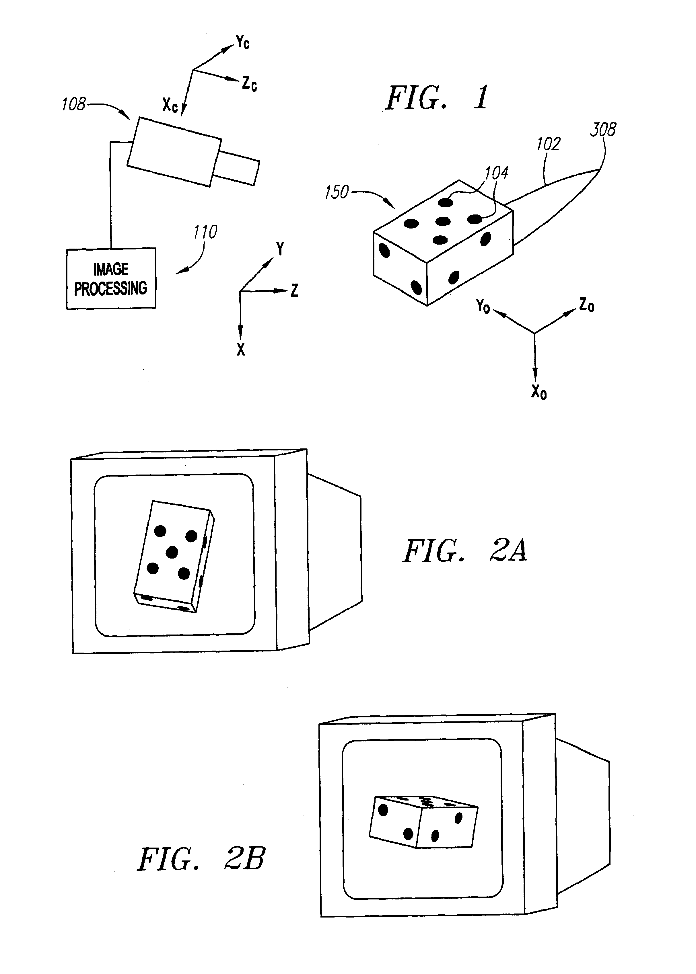
[0018]FIG. 1 depicts components of an embodiment of a system for detecting the position and orientation of an object or instrument 102. The object 102 comprises or is rigidly attached to a marker block 150 having three or more markers 104 located thereon or therein. An optical or video image apparatus, such as video camera 108, is aimed such that at least part of the marker block 150 is within the camera's field of view. Surfaces on marker block 150 include a combination of three or more markers that is or can be rendered visible to camera 108. The output data from camera 108 is sent to an image processing unit 110, which in one embodiment, comprises an analog / digital converter to generate digital pixel data, as well as a processor and storage components to manipulate, process, and store the image data.

[0019]According to an embodiment, camera 108 is placed on the ceiling, wall, or other support structure with its pointing angle adjusted to cover the working volume of interest. For p...


PUM


Abstract

A method and system for determining the position and orientation of an object is disclosed. A set of markers attached or associated with the object is optically tracked and geometric translation is performed to use the coordinates of the set of markers to determine the location and orientation of their associated object.

Description

CROSS-REFERENCE TO RELATED APPLICATIONS[0001]The present application is a continuation-in-part of U.S. application Ser. No. 09 / 893,122, filed Jun. 26, 2001, which is continuation-in-part of U.S. application Ser. Nos. 09 / 178,383 filed Oct. 23, 1998 now U.S. Pat. No. 6,621,389, and is a continuation in part of 09 / 178,385, filed Oct. 23, 1998, now U.S. Pat. No. 6,279,579, issued on Aug. 28, 2001, and is a continuation in part of 09 / 712,724 filed Nov. 14, 2000, now U.S. Pat. No. 6,690,965, which is a continuation of U.S. application Ser. No. 09 / 178,384 filed Oct. 23, 1998, now abandoned.BACKGROUND AND SUMMARY[0002]The present invention relates to methods and systems for determining the position and orientation of an object in 3-dimensional space.[0003]There are many applications where detection and tracking of the location and orientation of an object is desired. One approach for accomplishing this involves using multiple cameras to determine the location of a specific point in space vi...

Claims


Application Information

Patent Timeline
Patent Type & Authority Patents(United States)
IPC IPC(8): A61B5/055G01B11/00A61B5/11A61B6/00A61B8/00A61B19/00A61N5/10G01B11/03G01B11/26G01C11/02G01S3/786G01S5/16G01S17/66G06T1/00G06T17/00H04N
CPCA61B6/463A61B6/541A61N5/1048A61N5/1049G01C11/02G01S3/7864G06T7/0042A61B6/5247A61B5/055A61B5/11A61B5/1114A61B5/1127A61B5/4818A61B5/7289A61B19/54A61B2019/5227A61N5/1064A61N2005/1059G01S5/163G01S17/66G06T2207/30196G06T2207/30204A61B2090/371A61B90/39G06T7/73A61B8/4263
Inventor MOSTAFAVI, HASSAN
Owner VARIAN MEDICAL SYSTEMS
Why Eureka
Try Eureka