Distributed network repeater system

Inactive Publication Date: 2005-12-06
CISCO TECH INC
View PDF44 Cites 14 Cited by
  • Summary
  • Abstract
  • Description
  • Claims
  • Application Information

AI Technical Summary

Benefits of technology

[0012]According to one aspect, the repeater is configured to increase the size of the IPG between every pair of packets which are repeated by the repeater, to assist in reducing or avoiding instances of IPGs which are too short.
[0013]In one aspect of the invention, a repeater, useable for connecting switches in a data communication network, is provided in a distributed and/or modular fashion. The repeater includes a plurality of separate and distinct components or modules connected to, or at

Problems solved by technology

This configuration can be problematic when the space which is available for accommodating network equipment is limited and/or costly because the monolithic or undistributed repeater device will typically occupy a contiguous and relatively large portion of such space.
The problem is exacerbated by the fact that repeaters (especially high-bandwidth repeaters such as repeaters configured for a bandwidth of 1 gigabit per second or more) are typically provided in substantially non-modular form, e.g. are available in a relatively few sizes (both in terms of physical size and the number of ports or connections supported).
In such situations, it is impossible or infeasible for a user to be able to obtain a repeater of substantially the currently-req

Method used


Image

  • Distributed network repeater system
  • Distributed network repeater system
  • Distributed network repeater system

Examples


Embodiment Construction

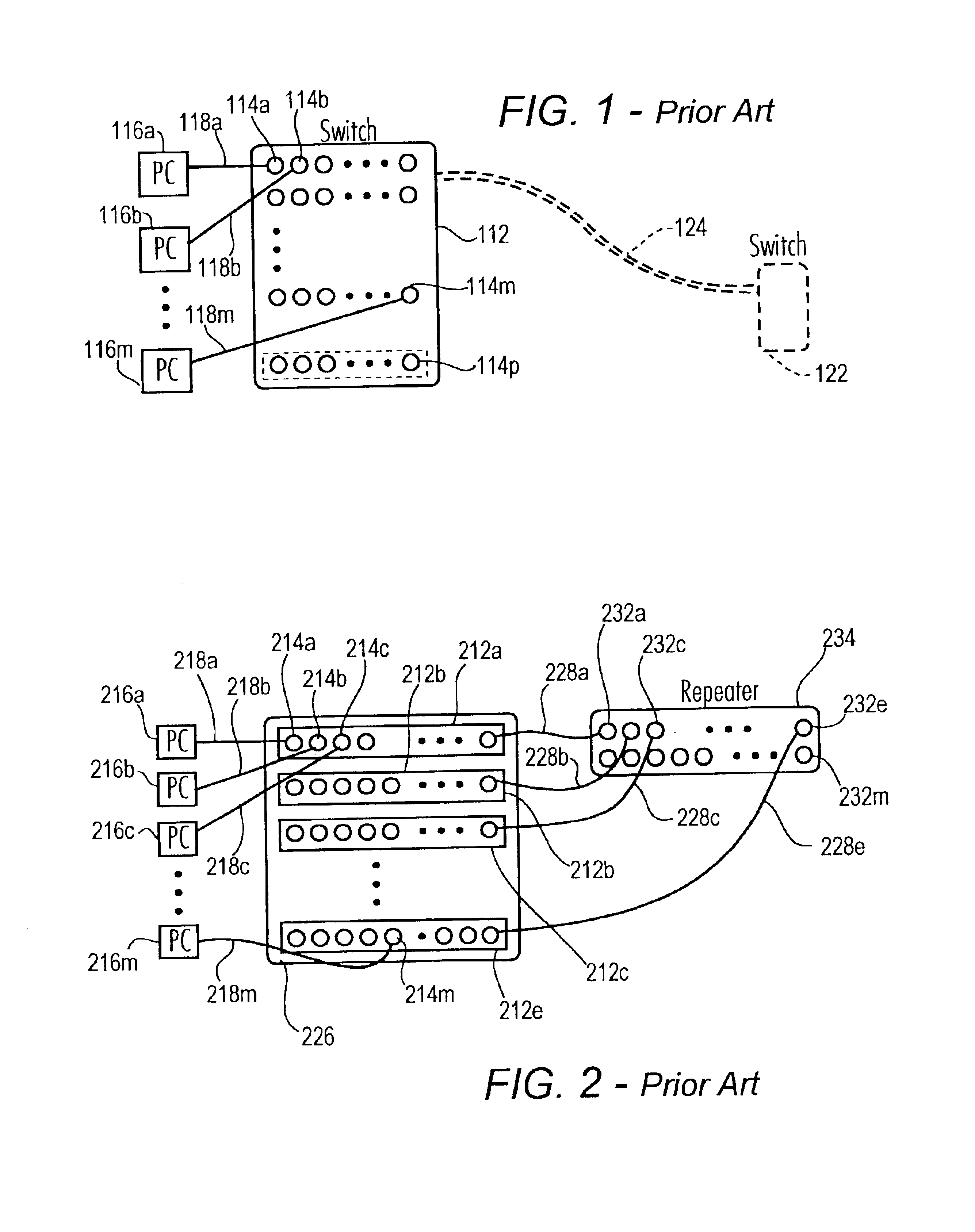
[0024]As depicted in FIG. 1, a common configuration of previous networks included a switch 112 having a plurality of ports 114a, b, m, p coupled to a variety of network nodes, illustrated, in FIG. 1, by personal computers (PCS) 116a, b, m. Nodes can include a variety of items including printers, scanners and the like. Depending, at least in part, on the type of network implemented, the connections can be way of cables 118a, b, in, such as coaxial cables, twisted pairs, optical fiber, or one or more wireless links and the like. Often, networks are configured to effectively place limits on the length of the node-connecting cables 118a, b, m and accordingly, in many configurations, the switch 112 must be positioned within a predetermined distance from the nodes 116a, b, m. When it is desired to also include nodes positioned beyond such distance, commonly one or more additional switches 122 are placed in a remote location, often coupled by a link such as an optical fiber link 124. In th...


PUM


Abstract

A repeater, useable for connecting switches in a data communication network, is provided in a distributed and/or modular fashion. The repeater includes a plurality of separate and distinct components or modules connected to or at least partially housed in, the various switches which the repeater modules couple. Preferably, the repeater autodetects and/or autoconfigures some or all aspects of repeater operations, such as detecting and/or configuring appropriate full/half-duplex mode operation or detecting and/or configuring in response to appropriate or approved cable-type connections. The distributed and/or modular repeater facilitates accommodating various switching or repeater needs as a network grows or contracts.

Description

CROSS-REFERENCE TO RELATED APPLICATION[0001]This application is a divisional of U.S. Patent Application Ser. No. 09 / 321,066 filed May 27, 1999, now U.S. Pat. No. 6,600,727 in the name of Gordon Mackay, and entitled “DISTRIBUTED NETWORK REPEATER SYSTEM,” which is incorporated herein by reference in its entirety and for all purposes.FIELD OF THE INVENTION[0002]The present invention relates to a system, method and apparatus for a computer network repeater system, apparatus and method and in particular to a repeater system which is distributed, and preferably modular, in nature.BACKGROUND OF THE INVENTION[0003]Repeaters provided in computer or other networks, such as local area networks (LAN), wide area networks (WAN), telecommunications networks and the like, have typically been provided in monolithic or nondistributed fashion such as providing a single chassis or cabinet for a repeater to which the various signal sources / destinations are coupled e.g. via cables and the like. This conf...

Claims


Application Information

Patent Timeline
IPC IPC(8): H04B3/60
CPCH04B3/60Y10S439/955
Inventor MACKAY, GORDON
Owner CISCO TECH INC
Why Eureka
Try Eureka