
Execution of extended activity diagrams by code generation

a technology of extended activity and code generation, applied in the direction of source code creation/generation, program control, multi-programming arrangements, etc., can solve the problems of complex sequence of steps, inability to represent complex flow management inherent in real-world activities with conventional modeling tools, and conventional modeling tools typically do not offer functionality to represent complex flow management inherent in real-world activities. to achieve accurate representation of run-time characteristics

Inactive Publication Date: 2005-12-06
IBM CORP
View PDF24 Cites 61 Cited by
  • Summary
  • Abstract
  • Description
  • Claims
  • Application Information

AI Technical Summary

Benefits of technology

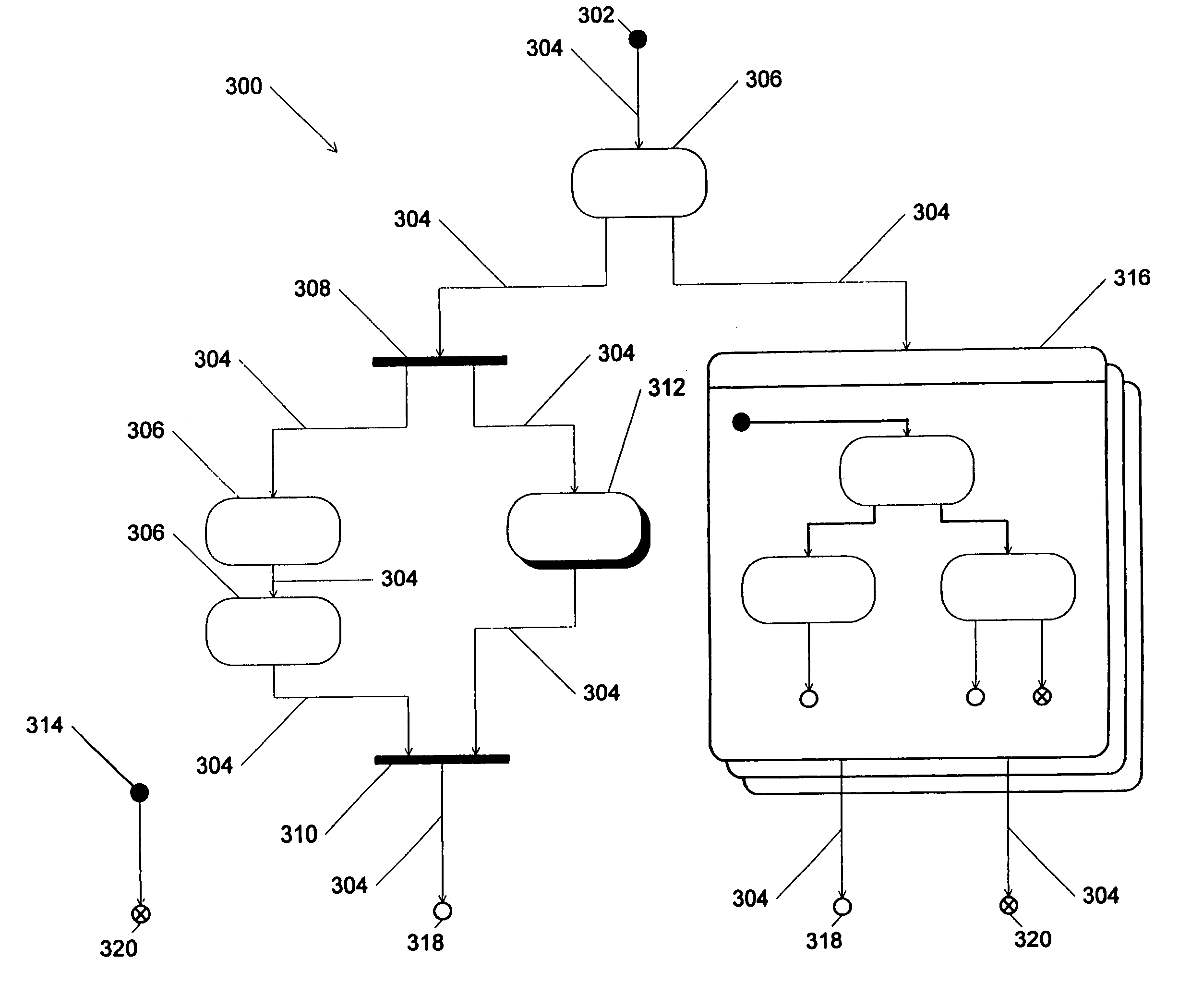
[0017]The invention includes numerous advantages. One advantage is that the process modeling tool enables a user to define a business processes using simplistic process flow techniques. The code generation portion of the tool takes advantage of the object orientation of the underlying run-time infrastructure. Simplistic process flow visual notations have been extended to model some of the capabilities of the underlying infrastructure to enable users to accurately represent the run-time characteristics of a business process (for example, “splits” to allow parallelization and “joins” for synchronizing events). This lets users represent complex processes without having to write complicated object oriented programming code. The modeling tool provides a way to bridge the gap between the power of object oriented infrastructure and the simplicity of process models to represent business logic. Hereto before, users had to use either complex object oriented modeling techniques or use simplistic process modeling tools which would generate (run on) inefficient code (infrastructure).

Problems solved by technology

In real world interactions, the sequence of steps is often complex, especially when modeling a prospective interaction rather than one which has already occurred.
These complications are difficult to represent with conventional modeling tools which are more suited to linear interactions.
Conventional modeling tools typically do not offer functionality to represent the complex flow management inherent in real world activities in a easily usable and understandable manner.
Simple flow charts are generally not adequate to display these processes.
However, conventional activity diagrams are limited in that they typically do not provide a representation for exceptions (errors arising during an interaction or activity), events occurring independently of actions, repetitive actions, or compensating actions, such as rollback procedures.

Method used


Image

  • Execution of extended activity diagrams by code generation
  • Execution of extended activity diagrams by code generation
  • Execution of extended activity diagrams by code generation

Examples


Embodiment Construction

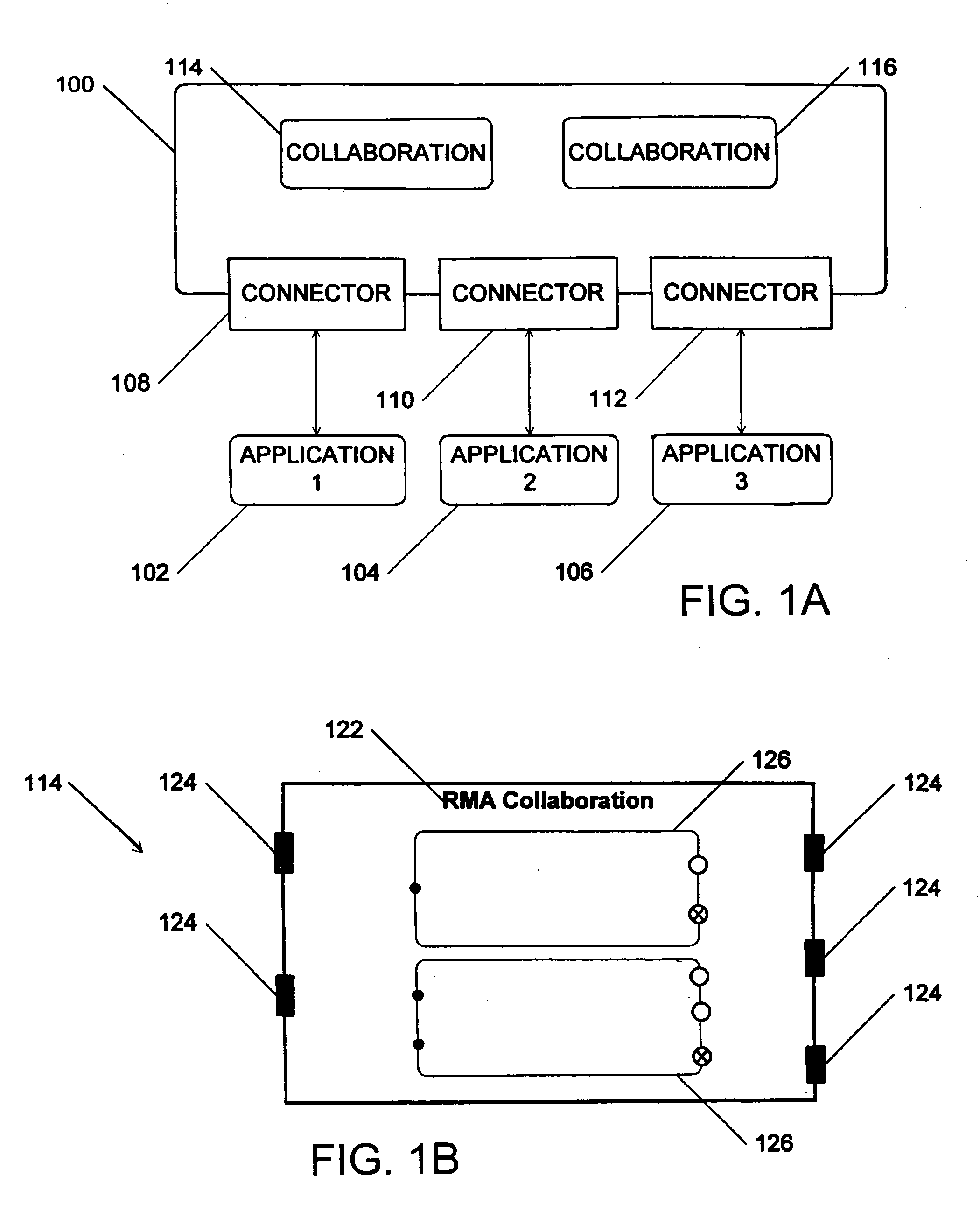
[0040]The preferred embodiment of the present invention may operate in the context of a collaboration architecture as disclosed in commonly owned U.S. patent application Ser. No. 08 / 780,593, titled “Modular Application Collaboration”, which is hereby incorporated by reference. The preferred embodiment is used to design and model processes encompassed within collaborations as defined in the above-referenced application.

[0041]In general, the collaboration architecture supports the interaction of independent applications which would be incompatible and could not directly interact with one another on their own. An example of the structure of a collaboration architecture is shown in FIG. 1A. A collaboration architecture provides an interchange server 100 for interaction between independent applications 102, 104, 106. Interchange server 100 preferably operates between applications 102, 104, 106 where applications 102, 104, 106 are connected to interchange server 100 by corresponding conne...


PUM


Abstract

A process modeling tool for graphically representing a process which includes transactions and events, and for generating computer code representing the process. A graphical tool creates a graphical representation of the transactions and events with graphical symbols, where one or more of such transactions and events may be of an asynchronous nature. A code generator generates computer code in response to information contained in the graphical representation. The computer code is executable on a computer system to cause the computer system to perform one or more operations which emulate the process shown in the graphical representation.

Description

[0001]This application is a continuation of Ser. No. 09 / 042,387 filed Mar. 12, 1998.[0002]The invention relates to process modeling and more particularly to the graphical representation of processes and the generation of executable code from such a representation.BACKGROUND OF THE INVENTION[0003]An interaction between multiple parties typically includes a sequence of steps. A graphical representation is a useful tool for illustrating the content of such an interaction. By showing the steps in a visual form observers as well as participants often more clearly understand the nature of the interaction taking place.[0004]In real world interactions, the sequence of steps is often complex, especially when modeling a prospective interaction rather than one which has already occurred. Multiple possible resolutions may arise at each step. In addition, events may arise asynchronously or in parallel. These complications are difficult to represent with conventional modeling tools which are more...

Claims


Application Information

Patent Timeline
IPC IPC(8): G06F9/44
CPCG06F8/34
Inventor GANGOPADHYAY, DIPAYANGUPTA, PRASHANTMAHBOD, HALEHPRABHUDESAI, ANANT VASANTSURESH, SRINIVASANWONG, WILLIAM WEI MAN
Owner IBM CORP
Learn More