Paintball guns

a paintball gun and paintball technology, applied in the field of paintball guns, can solve the problems of multiple shots to be fired, limited life, high failure rate of mechanical switches,

Inactive Publication Date: 2005-12-13
NPF
View PDF11 Cites 43 Cited by
  • Summary
  • Abstract
  • Description
  • Claims
  • Application Information

AI Technical Summary

Benefits of technology

[0012]Preferably, the sensing means is an optical sensing means. However, other forms of

Problems solved by technology

Typically, mechanical switches have suffered high failures due to wear, fatigue, contamination of the faces and corrosion.
However, they have a limited life due to mechanical wear of the integral spring mechanism, which leads to switch bounce, which is an undesired oscillation of the switch mechanism.
This, in turn, leads to rapid making and breaking of the switch contact, known as contact flutter, which can cause multiple shots to be fired when only one is intended.
Other pro

Method used


Image

  • Paintball guns
  • Paintball guns
  • Paintball guns

Examples


first embodiment

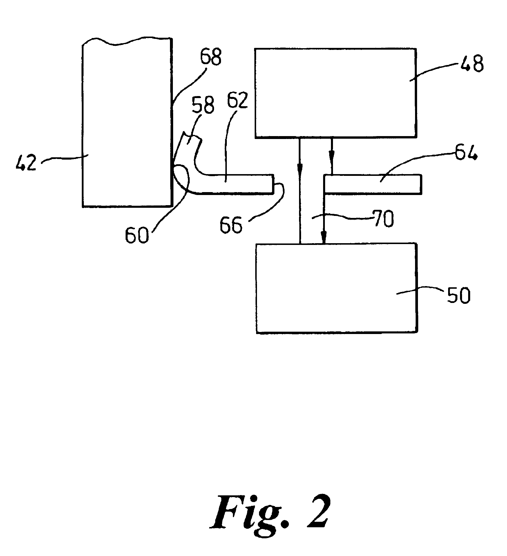
[0059]Referring to FIG. 2a, in a modification to the first embodiment, the trigger 42a includes a projection 64a on its rear edge, which is formed integrally with it and acts as the actuation member, extending between the optical emitter 48a and collector 50a. The projection 64a has a hole 66a drilled through it which performs the same function as the aperture 66 in the embodiment of FIG. 2. In a further modification, the spring or trigger may not have an aperture, but may simply have an end that moves between the emitter and collector during either pulling or releasing of the trigger.

[0060]It will be appreciated that various other modifications can be made to the embodiment described above. For example, instead of being set up so that the light from the emitter 48 reaches the collector 50 when the trigger 42 is depressed, but not when it is released, the system can equally be set up so that light from the emitter 48 reaches the collector 50 when the trigger 42 is released, but is b...

fourth embodiment

[0063]Referring to FIG. 6, in the invention, the trigger sensor comprises a piezoelectric sensor 220. This includes a piezoelectric crystal 222, which is arranged to have a force applied to it when the trigger 224 is pulled. The piezoelectric crystal is connected into an electrical circuit including two terminals 226, 228, and the application of a force to the crystal 222 causes it to produce an electric voltage between the terminals 226, 228 and hence the voltage can be measured and used to determine when the trigger 224 is being pulled or released.

fifth embodiment

[0064]Referring to FIG. 7, in a fifth embodiment-of the invention, the trigger position sensor comprises a strain gauge 230. This comprises a resistor 232, which is mounted on the trigger 234, and the resistance of which varies with the amount of strain experienced by the trigger 234. Pulling of the trigger 234, by a user, causes a force to be applied to a finger, engaging portion 236, and movement of the trigger is resisted by a spring 238 acting on an abutment portion 240 of the trigger 234. As the force applied increases, the spring 238 is compressed and the strain on the trigger 234 increases. This allows the position of the trigger 234 to be measured by measuring the resistance of the resistor 232. In a modification to this embodiment, the spring 238 can be replaced by a rigid stop so that applying a force to the trigger 234 does not cause it to move at all, but still increases the strain on the trigger as measured by the strain gauge 230. In this case, pulling and releasing of...


PUM


Abstract

A paintball gun trigger system includes a trigger, an emitter arranged to emit light and collector arranged to receive an amount of the light that varies with the position of the trigger and produce a signal that varies with the position of the trigger. A controller is arranged to determine from the signal when the trigger has been pulled and released. In one embodiment, the light beam from the emitter is pulsed on and off and the signal from the collector is sampled at regular intervals. Variations in the pulsed collector signal are used to detect when the trigger has moved to a pulled position and a released position, and when the collector is swamped with light from another source.

Description

BACKGROUND OF INVENTION[0001]The present invention relates to paintball guns, also referred to as paintball markers, and, in particular, to trigger systems for paintball guns.[0002]Paintball guns are generally operated by means of pressurized air and a family of these guns controls the firing of paintballs electronically. They, therefore, require some form of switch which is operated by a user actuating the trigger to produce a signal that initiates the firing cycle subject to any other logic criteria being meet, e.g., paintball sensing, circuit timing, bolt position, etc. The importance of the use of an electronic trigger is that the guns are required to operate at a very fast cycle time, typically with the ability to achieve rates of fire up to 30 shots per second. Also, the low force requirement of an electronic trigger enables the player to maintain high rates of fire relative to the lack of fatigue to the operator's trigger finger. Players, therefore, can achieve a very high nu...

Claims


Application Information

Patent Timeline
IPC IPC(8): F41A19/10F41A19/59F41B11/00F41B11/57
CPCF41A19/10F41A19/59F41B11/00F41B11/57
Inventor RICE, JOHN RONALD
Owner NPF
Why Eureka
Try Eureka