Apparatus for expressing milk

a technology of apparatus and milk, which is applied in the field of apparatus for extracting natural milk, can solve the problems of discomfort for users, inability to individually adjust, and the vacuum at the two collectors can only be adjusted at the pump, so as to reduce the size and weight of the pump, easy disassembly and cleaning, and easy reassembling

Inactive Publication Date: 2005-12-13
CLUTE L JASON
View PDF14 Cites 37 Cited by
  • Summary
  • Abstract
  • Description
  • Claims
  • Application Information

AI Technical Summary

Benefits of technology

[0015]A device for expressing milk from one or both breasts has at least one milk collector and a pump. Preferably, the device has first and second collectors (also called expressors), so that both breasts can be milked simultaneously. Each expresser has a cup assembly which fits on the breast, a pulsation port to which a supply of pressurized pulsating air is connected, and a vacuum port to which a vacuum supply is connected. The pulsating air and vacuum are created by the pump. In use, pulsating air massages the breast and stimulates milk production, while the vacuum secures the collector on the breast and helps express the milk from the breast.
[0016]A vacuum adjustment is provided on each collector, and a vacuum release is provided on one, and preferably each collector. In this manner, the vacuum can be individually adjusted, and easily released.
[0019]The bottom end of the case fits into a receptacle in the manifold. The receptacle has a boss which extends into the cup assembly by a desired distance. This boss prevents the liner from collapsing around the end of the nipple during use.
[0020]The collector can be easily disassembled and cleaned in a dishwasher or the like, by removing the collection vessel and using or storing the milk, removing the cap and vacuum adjustment / release valve, and then removing the cup assembly. The cup assembly can be cleaned without removing the liner, if desired, or the liner can be removed and cleaned separately, or replaced. A cleaning cap can be placed over the air pulsation port of the cup assembly when the cup assembly is cleaned in its assembled condition, to prevent water from entering the space between the liner and the case.
[0021]The manifold, cap and valve can also be washed. The cup assembly can be easily reassembled after cleaning by reinserting the cup assembly in the manifold, re-attaching the cap to the manifold and cup assembly, and securing another collection vessel to the bottom of the manifold, with the check valve.
[0022]The pump includes a movable diaphragm in a chamber. The diaphragm is oscillated back and forth by a linear actuator motor such as a stepper motor. The motor preferably has a shaft which does not rotate, but moves back and forth axially. The shaft of the motor is directly or nearly directly linked to the diaphragm, which eliminates complex and cumbersome linkage components, reducing the size and weight of the pump.

Problems solved by technology

However, the vacuum at the two collectors can only be adjusted at the pump, and cannot be individually adjusted.
This can create discomfort for the user if one breast is more sensitive than the other, or responds to stimulation differently than the other.
The Whittlestone patent does not disclose a vacuum release for the collectors.
As a result, when the device is turned off, the vacuum is broken by pulling the collectors from the breasts, or waiting for the vacuum to dissipate in order to remove the collectors.
This is inconvenient and sometimes uncomfortable.
The milk is drawn through vacuum lines, though, which makes cleaning difficult.
Moreover, the milk collecting vessels are reusable, and require frequent and thorough cleaning.
This design has limitations.
The liner is not accurately aligned and reliably sealed on the inlet side, so moisture and other contaminants can get inside the liner, which is undesirable.
At the outlet, the liner can collapse around the entire breast, including the tip of the nipple, which can be uncomfortable and can cause unnecessary trauma.
Rotation of the motor shaft is translated into back and forth action by a somewhat large and cumbersome linkage which moves the diaphragm.
This adds not only size but weight to the pump, as well.
This is a problem because storage and portability are desirable to breast pump users.

Method used


Image

  • Apparatus for expressing milk
  • Apparatus for expressing milk
  • Apparatus for expressing milk

Examples


Embodiment Construction

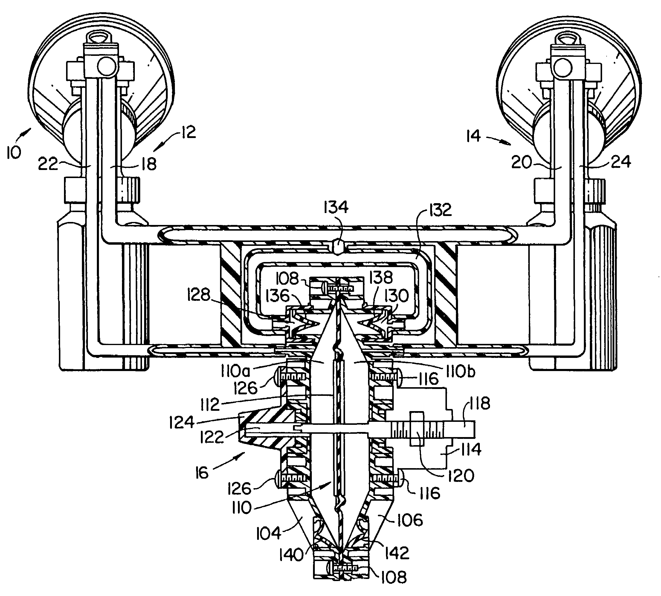
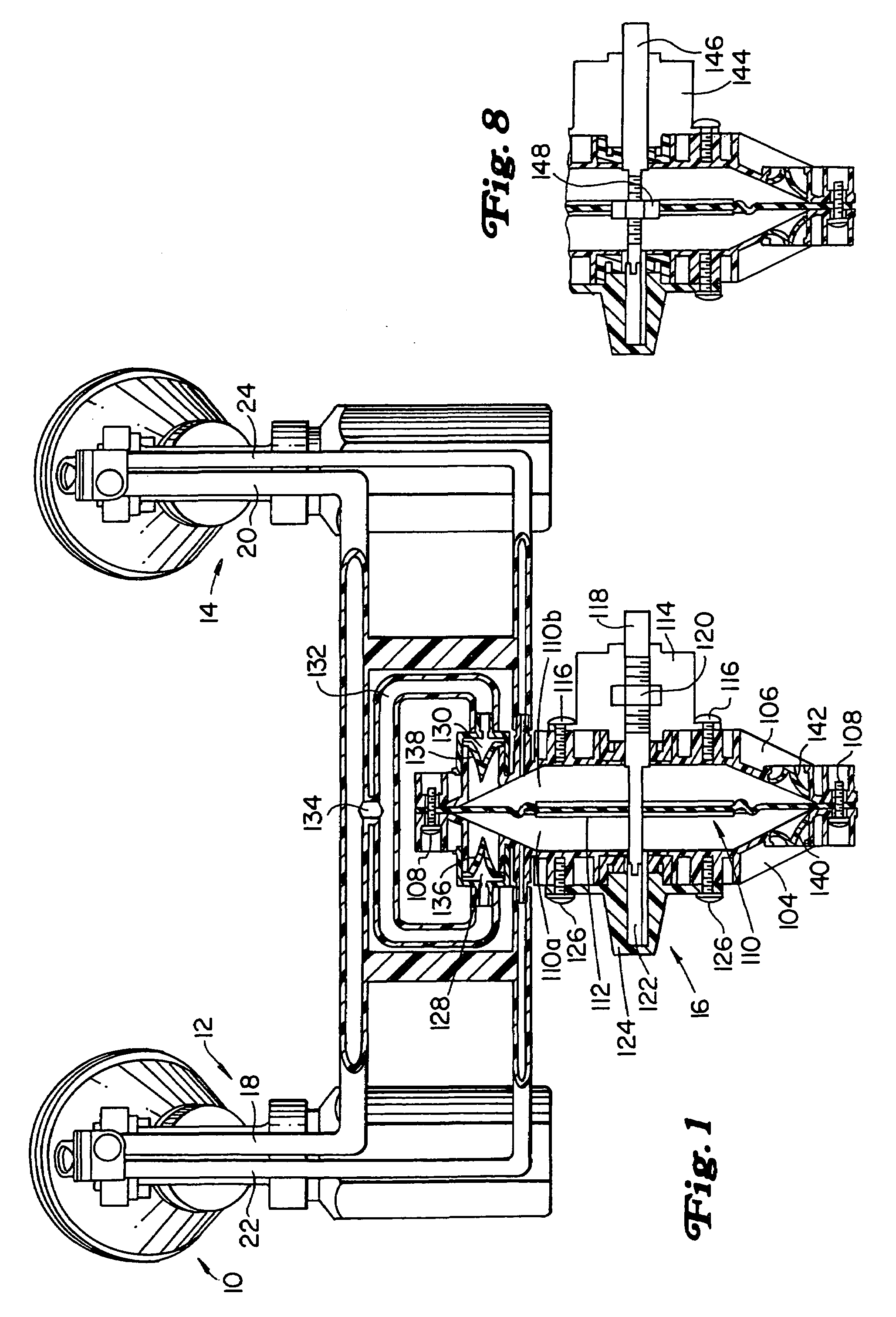
[0038]Referring to FIG. 1, apparatus 10 is provided for expressing milk from one breast, or from two breasts simultaneously. The apparatus 10 includes a first collector or expressor 12 and a second expressor 14. A pump 16 is connected to both expressors 12, 14 through vacuum lines 18, 20, and air pressure lines 22, 24.

[0039]The pump 16 creates a vacuum which engages the breasts, and contributes to drawing the milk from the breasts. The pump also creates pressure pulsation around the areola and some or all of the nipple, as will be seen. The pump 16 can be powered by line voltage, a battery, manually or the like.

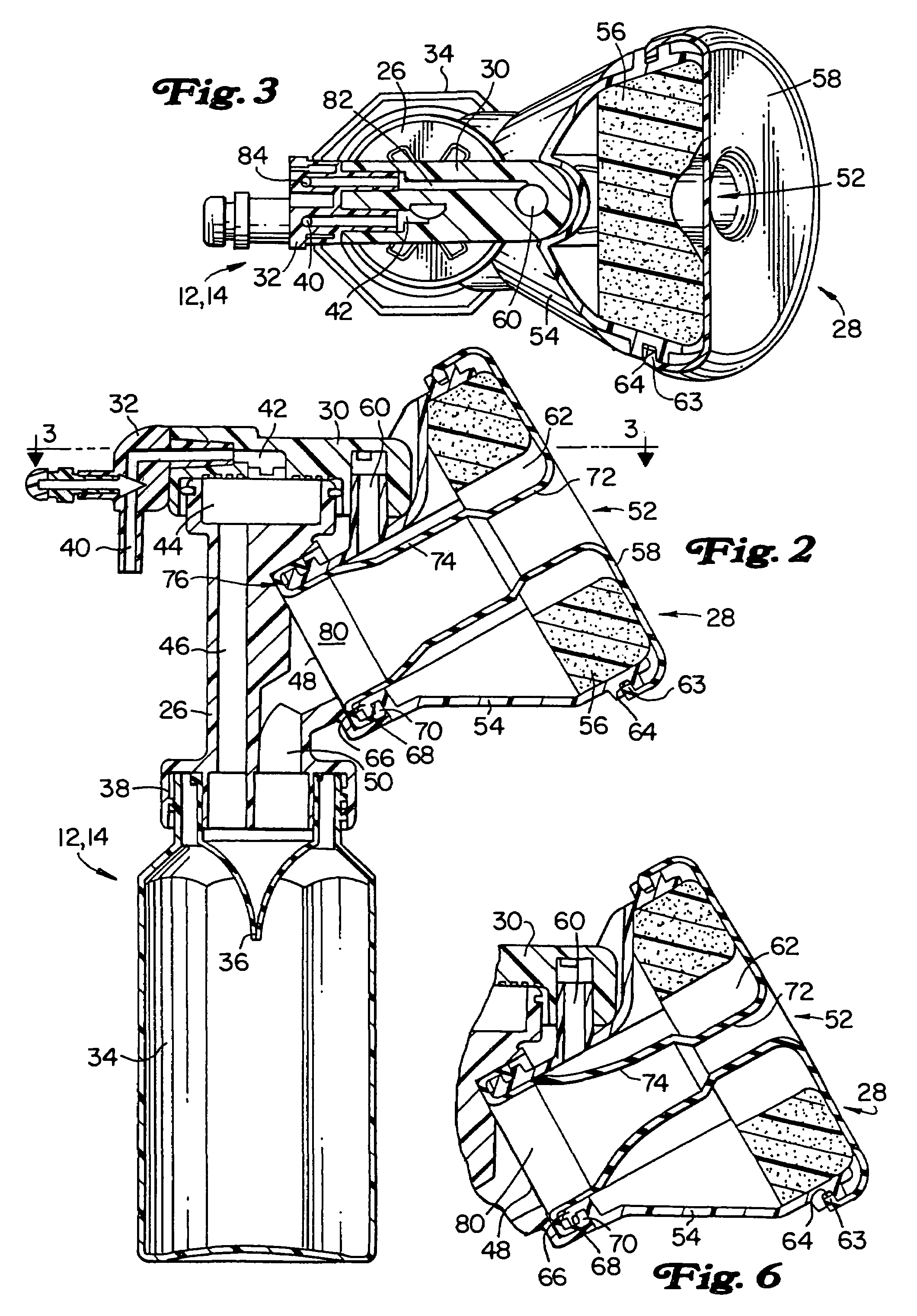
[0040]The expressors 12, 14 are shown in greater detail in FIGS. 2 and 3. Each expressor includes a manifold 26, a cup assembly 28 which fits over a breast, a cap 30, a filter 31, a vacuum adjustment release valve assembly 32, a sealing device 33 such as a wipe washer, o-ring or the like, a collection vessel 34 and a valve 36. The collection vessel can be a bottle made of pla...


PUM


Abstract

A device for expressing milk from one or more breasts has at least one, and preferably two expressors and a pump. The expressors each have a cup for fitting on the breasts and a cup outlet to which a vacuum created by the pump can be connected. A filter that is substantially permeable to air but substantially impermeable to milk and water prevents milk from entering the vacuum pump. The filter is preferably permeable to air even when wet, though, so that the device can still be operated, even as the filter collects fluid.

Description

[0001]This is a continuation-in-part of non-provisional application Ser. No. 09 / 591,981, filed Jun. 12, 2000, which is a of provisional application Ser. No. 60 / 140,902 filed Jun. 23, 1999.FIELD OF THE INVENTION[0002]This invention relates to apparatus for extracting natural milk, and more particularly, to breast pumps which are convenient and comfortable to use.BACKGROUND OF THE INVENTION[0003]Pumps for expressing milk from breasts are well-known. One known breast pump is disclosed in Whittlestone U.S. Pat. No. 4,607,596.[0004]The Whittlestone patent discloses a breast pump having two milk collectors connected to a pump which applies both a vacuum and pulsating pressure to the breasts to extract milk. The pulsating pressure massages the breast to stimulate milk production, and the vacuum secures the milk collectors to the breasts and helps draw the milk and collect it. However, the vacuum at the two collectors can only be adjusted at the pump, and cannot be individually adjusted. Th...

Claims


Application Information

Patent Timeline
Patent Type & Authority Patents(United States)
IPC IPC(8): A01J5/04A61M1/06
CPCA61M1/06A61M1/066A61M1/064A61M1/0697
Inventor MCKENDRY, BRUCE
Owner CLUTE L JASON
Why Eureka
Try Eureka