Efficient frequency compensation for linear voltage regulators

Active Publication Date: 2005-12-13
TEXAS INSTR INC
View PDF11 Cites 32 Cited by
  • Summary
  • Abstract
  • Description
  • Claims
  • Application Information

AI Technical Summary

Benefits of technology

[0005]This invention provides a frequency compensation technique that is particularly useful for high gain, high performance linear and/or low dropout voltage regulators which are inherently difficult to stabilize. According to one embodiment, the scheme includes two pieces, an inner loop compensation circuit and a circuit in parallel with one of the resistors in the output voltage divider. The advantages are smaller overall compensation elements, die area and cost savings, along with equal or improved phase margin and performance compared to regulators co

Problems solved by technology

The higher the performance and wider the conditions, then the harder it is to provide simple compensation schemes to keep the regulator stable.
There is also temperature variation and technology process uncertainty especially for the pass transistor which switches Vin to Vout.
It's hard to find simple, small, frequency compensation schemes, which are desirable for cost and co

Method used


Image

  • Efficient frequency compensation for linear voltage regulators
  • Efficient frequency compensation for linear voltage regulators
  • Efficient frequency compensation for linear voltage regulators

Examples


Embodiment Construction

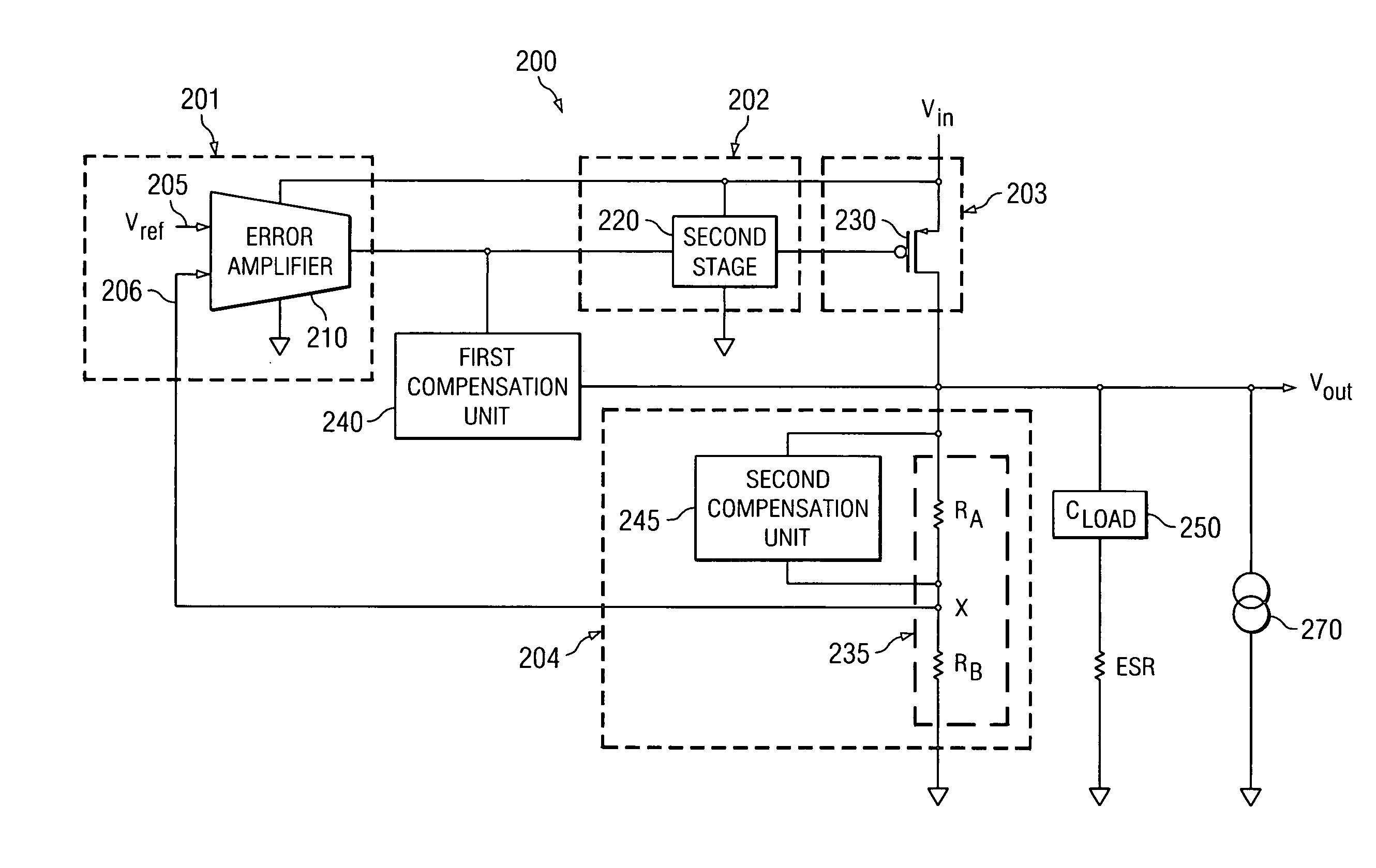
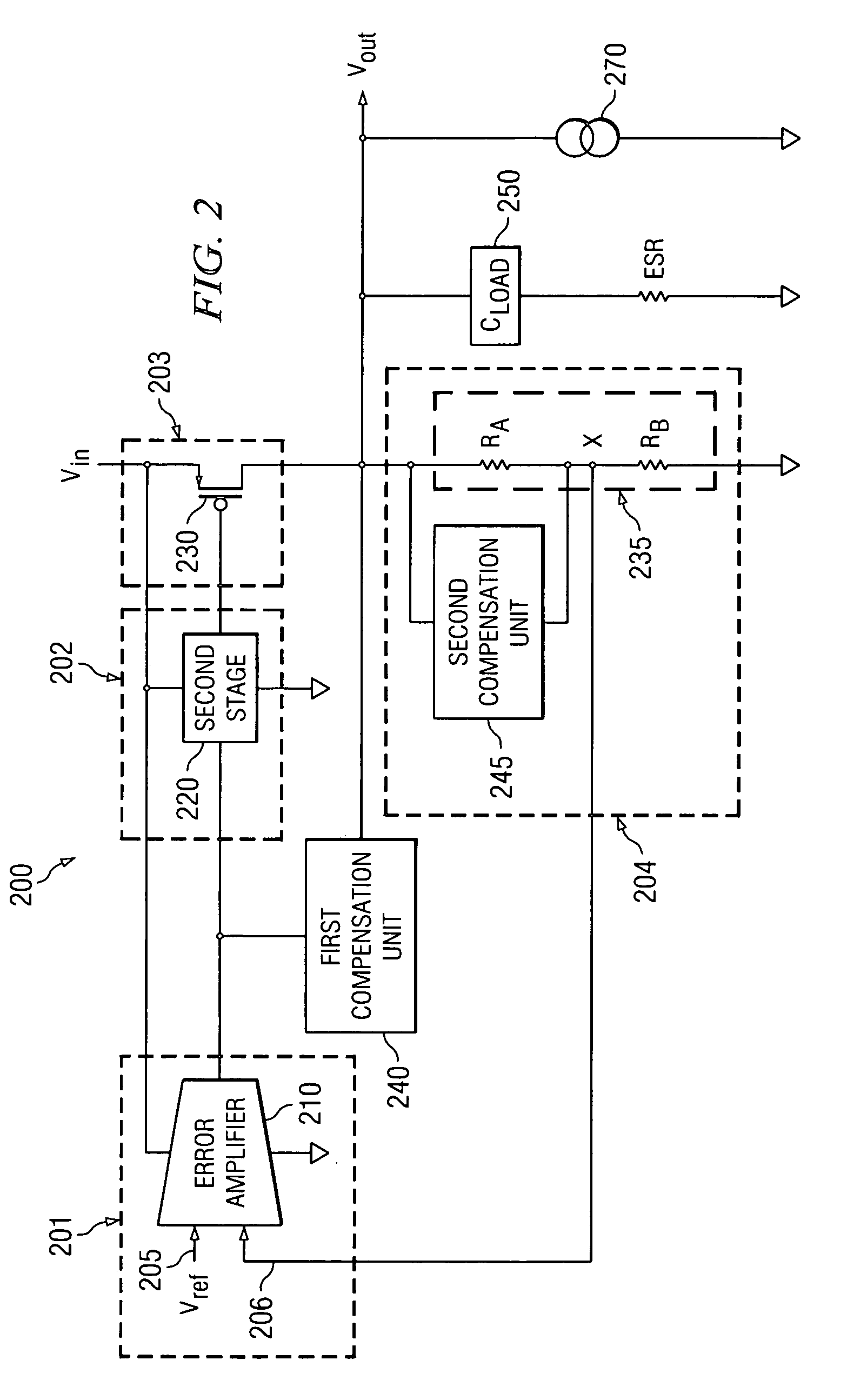
[0011]FIG. 2 illustrates an exemplary circuit for a voltage regulator 200 with a frequency compensation scheme for placing independent pairs of poles and zeros. The voltage regulator 200 includes three circuit stages, input stage 201, second stage 202, and output stage 203, along with voltage divider unit 204. The input stage 201 includes an error amplifier unit 210. The voltage divider unit 204 includes two resistors RA and RB. The second stage 202 is usually to drive the large input capacitance of the output stage. The second stage usually also contains gain for the regulator to maintain high overall gain when the gain of the output stage becomes very low under light current load conditions. The output stage 203 includes a large pass device transistor 230, usually a P-type or P-channel MOSFET, PMOS common source stage, or its equivalent P-type or PNP transistor for bipolar process technologies. For purposes of illustration, various elements of the voltage regulator 200 are shown a...


PUM


Abstract

The present application describes a frequency compensation scheme for a linear voltage regulator circuit, or its special case, a low-drop out voltage regulator (LDO). According to one embodiment, the frequency compensation scheme includes two circuits, an inner loop compensation circuit (240), and a circuit (245) at the output in parallel with one of the resistors of the output voltage divider (235). These two compensation elements (240, 245) are not interdependent and may be adjusted separately to provide more optimal frequency compensation. Advantages include smaller compensation circuit elements, die or board area savings, better phase margin over process technology variations and operating conditions, and ease of design adjustment.

Description

TECHNICAL FIELD[0001]The present application describes an improved frequency compensation scheme and specific embodiments of the scheme for linear and low dropout voltage regulators.BACKGROUND[0002]Linear voltage regulator circuits are used to create a clean, well regulated output voltage from some higher, noisy voltage supply source. Such regulator circuits are needed in most electrical systems to provide clean voltage, such as for industrial / automotive circuit applications where the environment is particularly noisy, or such as for wireless applications where the battery power fluctuates and frame synchronization glitches would become very apparent in the audio band.[0003]High performance linear regulator circuits generally have very high gain and need to be frequency compensated in order to have stable performance over a very wide range of operating conditions. The higher the performance and wider the conditions, then the harder it is to provide simple compensation schemes to kee...

Claims


Application Information

Patent Timeline
IPC IPC(8): G05F1/56G05F1/575
CPCG05F1/575
Inventor WU, DOLLY Y.GRANT, DAVID
Owner TEXAS INSTR INC
Why Eureka
Try Eureka