Efficient radome structures of variable geometry

a variable geometry, efficient technology, applied in the field of radomes, can solve the problems of reducing affecting the transfer characteristics of conventional radomes, and reducing the efficiency of radomes

Inactive Publication Date: 2005-12-13
NORTH SOUTH HLDG
View PDF32 Cites 13 Cited by
  • Summary
  • Abstract
  • Description
  • Claims
  • Application Information

AI Technical Summary

Problems solved by technology

Mismatches between the impedance of free space and the radome can result in energy dissipation at the point of incidence.
Relying upon such an impedance transform, however, results in radomes optimized for specific frequencies and places a limitation upon radome thickness.
The further the deviation from the optimized frequency, the greater the perturbations caused by the exemplary conventional radome; since the half-wavelength transform cannot properly function for differing wavelengths.
Differing angles of incidence also substantially affect the transfer characteristics of conventional radomes.
Consequently, performance of conventional radomes is significantly affected by various incident angles.
Other shapes would result in differing angles of incidence, thereby degrading radome performance characteristics.
A number of difficulties result from the necessity that conventional radomes be hemispherically shaped.
The coupling planes at which adjace...

Method used


Image

  • Efficient radome structures of variable geometry
  • Efficient radome structures of variable geometry
  • Efficient radome structures of variable geometry

Examples


Embodiment Construction

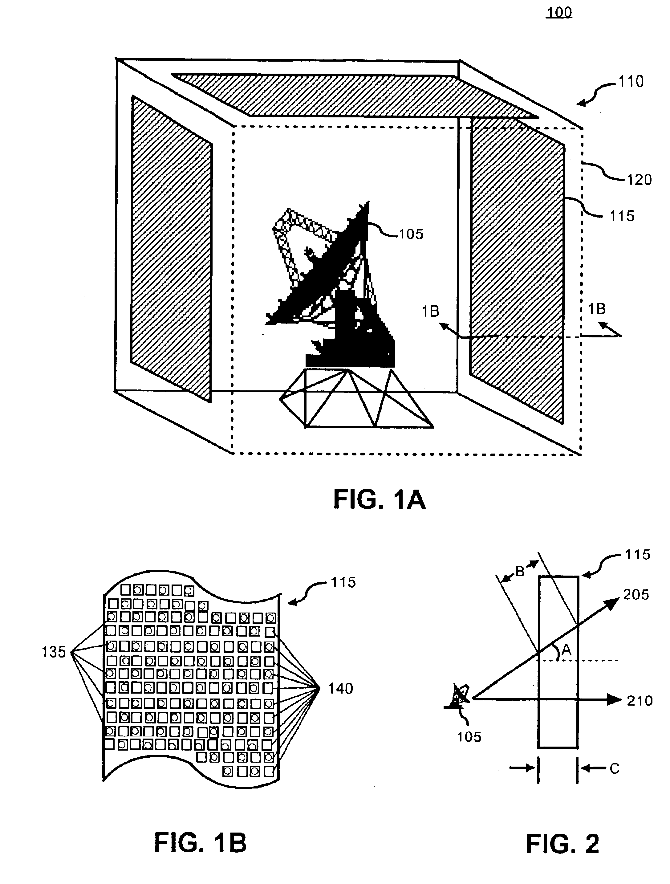
[0033]FIG. 1A is a schematic diagram illustrating an exemplary radome system 100 in accordance with the inventive arrangements disclosed herein. The system 100 can include an electromagnetic device 105 and a radome 110, which includes a radome wall 115 and a radome frame 120. The electromagnetic device 105 can be a transceiver coupled to an antenna.

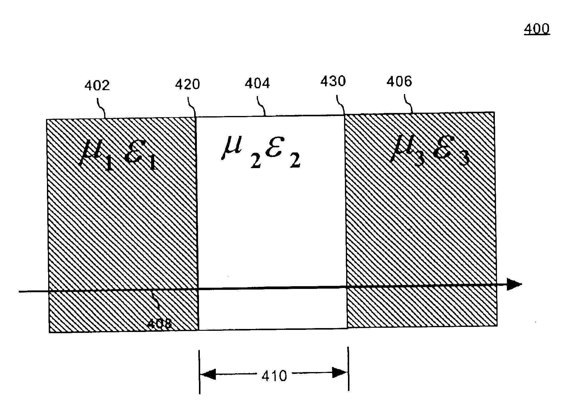
[0034]The radome 110 can be an environmental shell configured to be substantially transparent to radio frequency radiation in the frequency range of interest. The radome 110 protects the enclosed electromagnetic device 105 from environmental conditions. Radome 110 can be a variety of types including, but not limited to, a space frame radome, a sandwich radome, and a solid laminate radome. The radome 110 can be designed for particular performance characteristics relating to radio frequency radiation. For example, radome 110 can be impedance matched to the surrounding environment (i.e. free space). Accordingly, radome 110 need not utilize i...


PUM


Abstract

Method for constructing a radome (110). The method can include the steps of providing a radome structure, wherein the radome structure can include at least one of a radome wall (115) and a radome frame (120). The radome structure can be impedance matched to an operational environment. The impedance match can be independent of the thickness and geometry of the radome structure.

Description

BACKGROUND OF THE INVENTION[0001]1. Technical Field[0002]The present invention relates to the field of radomes, and more particularly to efficient radomes of variable geometry.[0003]2. Description of the Related Art[0004]Conventional radomes are typically dome-like shells that can be used to protect enclosed electromagnetic devices, such as antennas, from environmental conditions, such as wind, solar loading, ice, and snow. Radomes, such as a solid laminate and sandwich radomes, can be rigid self-supporting structures. Mismatches between the impedance of free space and the radome can result in energy dissipation at the point of incidence. The energy dissipation can be the result of a reflective wave being generated at a medium boundary, such as the radome / free-space boundary.[0005]If an electromagnetic wave strikes a medium boundary at a point which is multiple of a half wavelength, energy dissipation at the boundary can be minimized. A material which minimizes reflections across me...

Claims


Application Information

Patent Timeline
IPC IPC(8): H01Q1/42
CPCH01Q1/422
Inventor DELGADO, HERIBERTO JOSEKILLEN, WILLIAM D.
Owner NORTH SOUTH HLDG
Why Eureka
Try Eureka