
Novel heat exchange tube

A technology of heat exchange tubes and heat exchange pipes, applied in the direction of tubular elements, heat transfer modification, heat exchange equipment, etc., can solve the problems of increased system energy consumption, complicated processing technology, and increased loss along the process, and achieve the goal of exchanging Increased thermal coefficient, enhanced heat transfer effect, and reduced resistance loss

Inactive Publication Date: 2016-06-22
SHANGHAI OCEAN UNIV
View PDF10 Cites 3 Cited by
  • Summary
  • Abstract
  • Description
  • Claims
  • Application Information

AI Technical Summary

Problems solved by technology

Most of the special-shaped heat exchange tubes on the market currently have defects such as easy fouling, large pressure drop, and complicated processing technology due to the presence of built-in or external turbulence protrusions during operation.
Therefore, in the later operation process, the heat transfer performance will be greatly reduced
The method of increasing the heat transfer area density of the heat exchanger is a common method to enhance heat transfer, but the complex structure leads to increased loss along the process, which in turn leads to increased energy consumption of the system

Method used


Image

  • Novel heat exchange tube
  • Novel heat exchange tube
  • Novel heat exchange tube

Examples


specific Embodiment 1

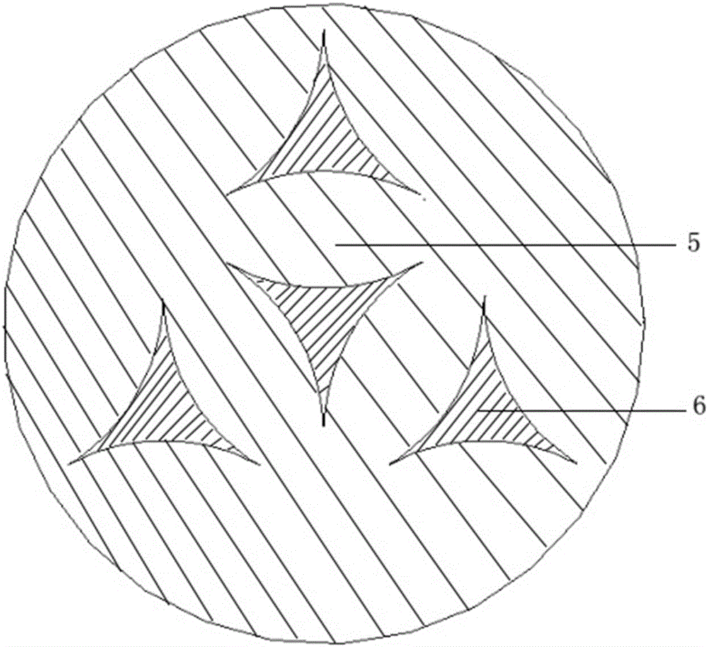
[0023] The cross-sectional shape of the pipe is formed by three equal circles with a radius of 25mm circumscribed in pairs; if the design requires that the B range is 550-1994m 2 / m 3 , the arrangement method 1 is adopted: equilateral triangle arrangement, the positional relationship between the pipe walls is as follows: take any one pipe geometric center as the rotation center, and the remaining three adjacent pipes are arranged rotationally symmetrically at a rotation angle of 120°, and the two adjacent pipes The axial center distance d is 30-40mm, and the length of the heat exchange tube is determined according to the design requirements of the heat exchanger. When the length of the heat exchange tube is less than 2m, the thickness of the tube wall is 2mm; When the ratio of the diameter a of the fluid inlet on the shell side of the heat exchanger to the length b of the heat exchange tube is less than 0.2, the included angle of the wall of the heat exchange tube shall be arr...

specific Embodiment 2

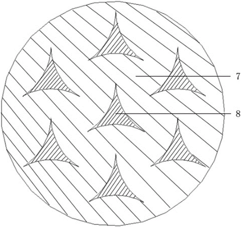
[0026] The cross-sectional shape of the pipe is formed by three equal circles with a radius of 25mm circumscribed in pairs; if the design requires that the range of B is 500-636m 2 / m 3 , using the second arrangement: regular hexagonal arrangement, with any one pipe geometric center as the center of rotation, and the other 6 adjacent pipes are arranged rotationally symmetrically at a rotation angle of 120°, and the axial center distance d of two adjacent pipes is 37- 45mm, the length of the heat exchange tube is determined according to the design requirements of the heat exchanger. When the length of the heat exchange tube is less than 2m, the thickness of the tube wall is 2mm; when the length of the heat exchange tube is greater than 2m, the thickness of the tube wall is 3mm; When the ratio of a to the length b of the heat exchange tube is less than 0.2, the included angle of the wall of the heat exchange tube shall be arranged in the direction of the incoming flow; the pipe ...


PUM


Abstract

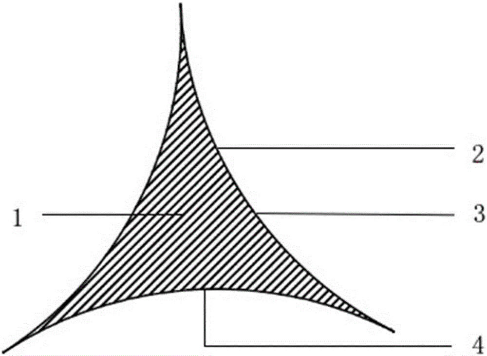
A new type of heat exchange tube, the heat exchange tube includes: flow channel (1), tube wall (2), tube wall (3), tube wall (4); the cross-sectional shape of the tube is composed of three equal circles with a radius of 25mm Formed by two circumcisions; the heat exchange tubes are composed of two different arrangements: regular triangle arrangement and regular hexagonal arrangement. The unique shape of the heat exchange pipe of the invention can increase the intensity of turbulent flow, strengthen the heat exchange effect, and improve the heat exchange performance. Compared with ordinary round pipes, the heat exchange coefficient is increased by nearly 50%. At the same time, the structure is relatively simple, it is not easy to scale, and it is more convenient to clean after scaling.

Description

technical field [0001] The invention belongs to the technical field of refrigeration / energy, and relates to a novel heat exchange tube, in particular to a special-shaped heat exchange tube which strengthens fluid disturbance and increases the heat transfer area density of a heat exchanger. Background technique [0002] Special-shaped heat exchange pipes, as a device to improve the efficiency of heat exchangers, have been widely used in the fields of energy / refrigeration / chemical industry in recent years, but there is still a lack of theoretical guidance in design and manufacture, and insufficient data in practical applications. Various manufacturers produce different types of special-shaped heat exchange pipes, but there is no relevant information on the reliability of the pipes, and the test data is yet to be verified. Jin Zunlong (Jin Zunlong, Three-dimensional Numerical Simulation of Enhanced Heat Transfer in Spiral Grooved Tube, Journal of Zhengzhou University (Engineeri...

Claims


Application Information

Patent Timeline
Patent Type & Authority Applications(China)
IPC IPC(8): F28F1/04F28F13/12F28F19/00
CPCF28F1/04F28F13/12F28F19/00
Inventor 谢晶李文俊王金锋徐旻晟李艺哲
Owner SHANGHAI OCEAN UNIV
Learn More