Plasma processing apparatus

A processing device and plasma technology, applied in the directions of plasma, coating, gaseous chemical plating, etc., can solve the problems of inability to stably supply plasma, insufficient cooling of antenna conductors, insufficient cooling of dielectric tubes, etc., and achieve easy maintenance and repair. , The shape is simple, the effect of preventing temperature rise

Active Publication Date: 2013-06-12
ELECTRO-MOTIVE DIESEL
View PDF10 Cites 3 Cited by
  • Summary
  • Abstract
  • Description
  • Claims
  • Application Information

AI Technical Summary

Problems solved by technology

However, in order to process the dielectric tube according to the shape of the antenna, high technology and high manufacturing cost are required
Furthermore, even when the refrigerant flows through the inside of the conductor tube to cool the antenna conductor as described above, the dielectric tube is not sufficiently cooled and may reach a very high temperature of several hundred degrees Celsius.
Therefore, the dielectric tube is easily damaged due to thermal stress, and the antenna conductor is not sufficiently cooled due to the propagation of heat from the dielectric tube, and the impedance of the antenna conductor increases, making it impossible to stably supply plasma.

Method used


Image

  • Plasma processing apparatus
  • Plasma processing apparatus
  • Plasma processing apparatus

Examples


Embodiment 1

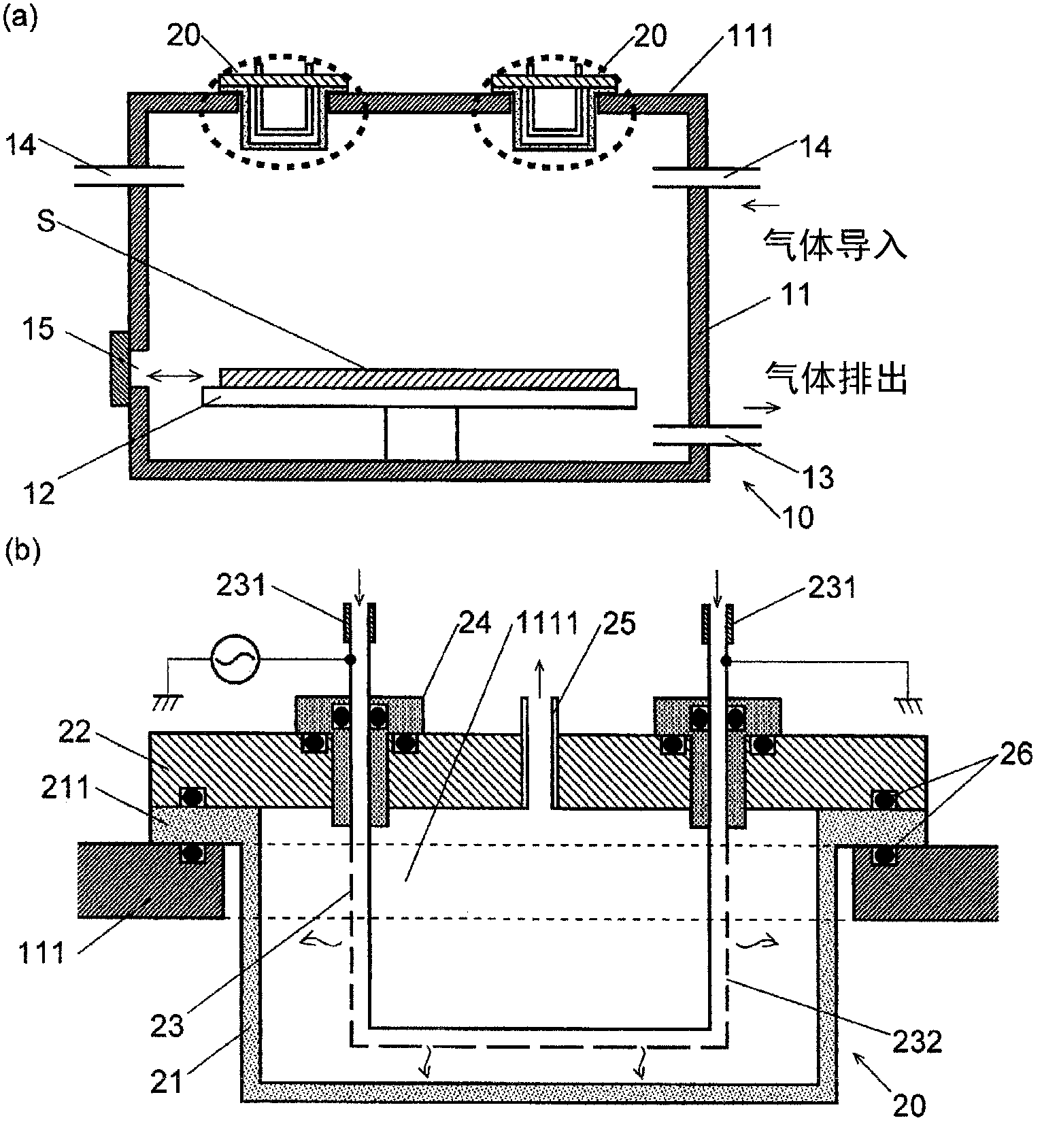
[0040] First, the plasma processing apparatus 10 of the first embodiment will be described. Such as figure 1As shown in (a), the plasma processing apparatus 10 is provided with a vacuum vessel 11, a substrate holding portion 12 arranged in the vacuum vessel 11, a first gas discharge port 13 and a first gas introduction port 14 provided on the side wall of the vacuum vessel 11. , and a plurality of antenna units 20 are provided on the upper wall 111 of the vacuum container 11 . The first gas outlet 13 is connected to a vacuum pump, and the air, water vapor, etc. in the vacuum container 11 are discharged from the first gas outlet 13 by means of the vacuum pump, thereby making the inside of the vacuum container 11 into a high vacuum state. The first gas introduction port 14 is used to introduce a plasma generation gas such as hydrogen gas or a source gas into the vacuum vessel 11 . The substrate S held by the substrate holding unit 12 is carried into or out of the vacuum contai...

Embodiment 2

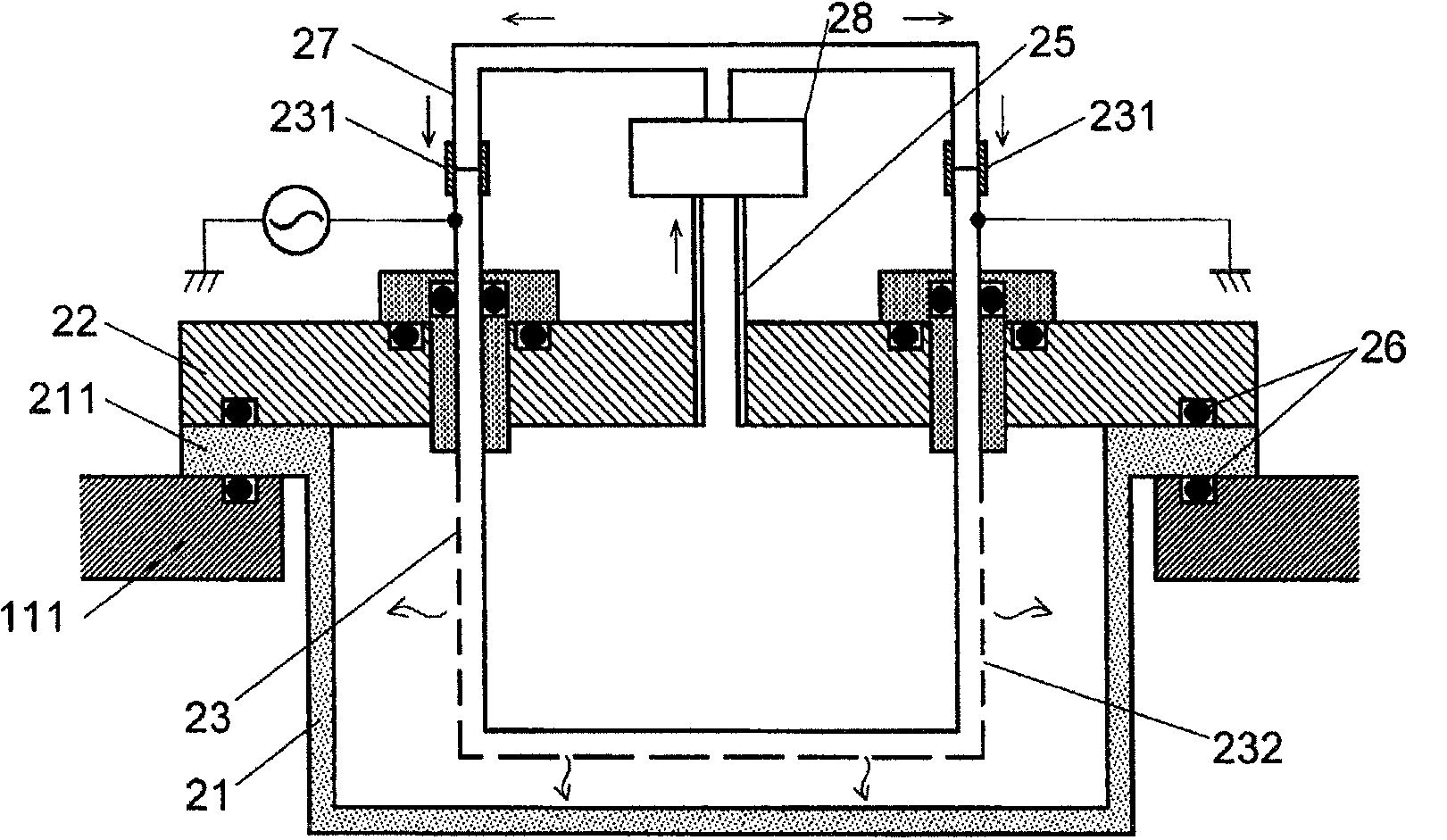
[0051] In the plasma processing apparatus 10 of the first embodiment, as image 3 As shown, the second gas outlet 25 is connected to the second gas inlet 231 by a connecting pipe 27, and a pump and a heat exchanger 28 may be provided between the two. Here, the second gas introduction port 231 connected to the high-frequency power source side and the connection pipe 27 are electrically insulated by interposing an insulator therebetween or forming the connection pipe 27 as an insulator. With such a configuration, the inert gas discharged from the second gas outlet 25 is cooled by the heat exchanger 28 and can be introduced again into the second gas inlet 231 , so that the inert gas can be circulated and reused. Furthermore, when economical efficiency is prioritized, the air can be circulated as cooling gas.

Embodiment 3

[0053] In the plasma processing apparatus 10 of the first embodiment, the dielectric housing 21 is attached so as to cover the opening 1111 of the vacuum vessel 11 from below, and the cover 22 is attached so as to cover the opening 1111 from above ( Figure 4 (a)). In this case, the flange portion 211 of the dielectric frame 21 is fixed to the lower surface of the upper wall 111 , and the cover 22 is fixed to the upper surface of the upper wall 111 . Alternatively, the dielectric frame 21 may be installed on the lower surface of the upper wall 111 having no opening ( Figure 4 (b)). In this case, the high-frequency antenna 23 is fixed to the upper wall 111 . Also, no cover is required.


PUM


Abstract

The present invention provides an internal antenna type plasma processing device which is easily maintained and capable of producing stable plasma. The plasma processing device has a plurality of antenna units 20 provided in the top wall 111 of a vacuum chamber 11. Each of the antenna units 20 includes: a dielectric housing 21 provided to protrude into the vacuum chamber 11 from the top wall 111 of the vacuum chamber 11; a cover 22 having a second gas discharge port 25 for discharging the atmosphere in the housing to the outside of the vacuum chamber; and a radio-frequency antenna 23 formed by a conductor tube which is fixed to the cover 22 by way of a feedthrough 24 and has gas passage holes 232 in its tube walls. An inert gas is supplied into the tube of the radio-frequency antenna 23, and the inside of the housing 21 is filled with the inert gas provided through the gas passage holes 232. The inert gas is discharged to the outside of the vacuum chamber 11 through the second gas discharge port 25.

Description

technical field [0001] The present invention relates to an inductively coupled plasma processing apparatus that can be used for substrate surface processing and the like. Background technique [0002] Conventionally, a plasma processing apparatus has been used in order to perform a film formation process for forming a thin film on a substrate and an etching process for a substrate. In the plasma processing apparatus, there is a capacitively coupled plasma processing apparatus that generates plasma by using an electromagnetic field generated by applying a high-frequency voltage between electrodes, and a plasma processing apparatus that uses an electromagnetic field generated by passing a high-frequency current through a high-frequency antenna (coil). Inductively coupled plasma processing equipment that generates plasma, etc. Among them, the capacitive coupling type plasma processing device has the advantage of lower cost than the device of the inductive coupling type structu...

Claims


Application Information

Patent Timeline
Patent Type & Authority Applications(China)
IPC IPC(8): H05H1/46C23C16/505H01L21/205H01L21/3065
CPCH01J37/3211H05H1/46H05H1/4652H01J37/32082
Inventor 江部明宪渡边正则
Owner ELECTRO-MOTIVE DIESEL
Why Eureka
Try Eureka