Method and apparatus for non-destructive testing

a non-destructive testing and apparatus technology, applied in the direction of optical radiation measurement, instruments, material magnetic variables, etc., can solve the problems of difficult identification of deficiency and inability to properly pickup images, and achieve the effect of easy finding the position of deficiency

Inactive Publication Date: 2005-12-13
RICOH PRINTING SYST +1
View PDF8 Cites 15 Cited by
  • Summary
  • Abstract
  • Description
  • Claims
  • Application Information

AI Technical Summary

Benefits of technology

[0009]It is also an object of the invention to provide a deficiency inspection method, a deficiency inspection appar...

Problems solved by technology

If a color video camera is used directly, however, it cannot pickup an image properly in the penetrant inspection because of the irradiation-oriented regular reflection light from the...

Method used


Image

  • Method and apparatus for non-destructive testing
  • Method and apparatus for non-destructive testing
  • Method and apparatus for non-destructive testing

Examples


Embodiment Construction

[0028]A preferred embodiment of the invention will now be described with reference to the accompanying drawings.

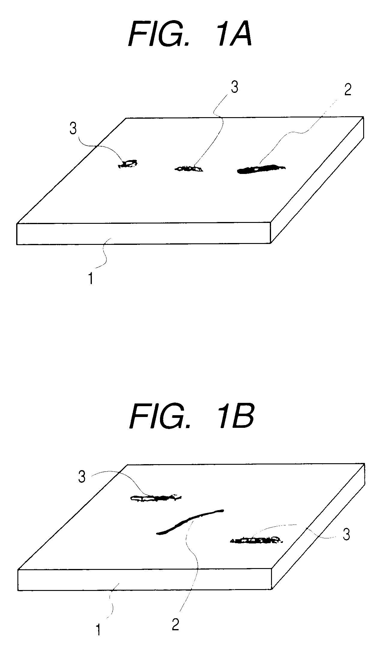
[0029]FIG. 1 shows one example of a deficiency which is inspected in the invention.

[0030]FIG. 1A shows one example of a penetrant inspection image, a white penetrant is applied to a specimen 1, a deficiency 2 (high contrast) and pseudo deficiencies 3 (low contrast) are observed. In the penetrant inspection, the deficiency 2 is highlighted as a red indicated pattern. The pseudo deficiencies appear when the penetrant stays in surface-polishing originated lines or the like and cannot be wiped out clean, and becomes a light red indicated pattern.

[0031]FIG. 1B shows one example of a magnetic-particle inspection image, and it is assumed that a deficiency 2 exists on a specimen and fluorescent magnetic powder has already been applied and magnetized. When ultraviolet rays are illuminated on it, the fluorescent magnetic powder that has gathered on the deficiency 2 due to magnetizat...


PUM


Abstract

Using an image signal acquired by picking up a sample to be inspected by a color video camera, penetrant inspection and magnetic-particle inspection, which are non-destructive inspections, are carried out so that deficiency candidates, including a pseudo deficiency, are automatically detected and displayed on a screen. A real deficiency can be detected from the displayed deficiency candidates. As image data is stored in memory means, information of a deficiency can be repeatedly reproduced on the screen. In the penetrant inspection, the chromaticity at each position on an image is acquired, a deficiency candidate is extracted based on the chrominance, and the deficiency is distinguished from a pseudo deficiency based on the differential value of the chrominance. A polarization filter eliminates regular reflection originating from illumination in the penetrant inspection, and an ultraviolet-rays cutting filter prevents noise in the magnetic-particle inspection. Both inspections can be carried out with a single probe.

Description

TECHNICAL FIELD[0001]The present invention relates to a method of inspecting a deficiency, such as a crack in a metal surface, and, more particularly, to an inspection method for performing non-destructive inspections called penetrant inspection and magnetic-particle inspection and an apparatus therefor.BACKGROUND ART[0002]A penetrant inspection and magnetic-particle inspection inspect a deficiency, such as a crack (crack) having an opening in the surface of metal in a non-destructive manner. In the penetrant inspection, normally, a red liquid called penetrant is applied to the surface to be inspected, the penetrant is wiped out after a predetermined time passes, and white powder called a developer is applied. If there is a deficiency, such as a crack, the penetrant remaining in the crack comes to the surface due to capillary phenomenon, indicating a deficiency in red. In case of magnetic-particle inspection, a solution containing fluorescent magnetic powder is sprayed on a specimen...

Claims


Application Information

Patent Timeline
IPC IPC(8): G01N21/00G01N21/88G01N21/91G01N27/84
CPCG01N21/8806G01N21/91G01N27/84G01N2021/8845G01N2021/8918
Inventor ASANO, TOSHIOSAKAI, KAORUTAGUCHI, TETSUOTANAKA, ISAO
Owner RICOH PRINTING SYST
Why Eureka
Try Eureka