Disk apparatus

a technology of a disk and a sleeve, which is applied in the field of sleeve apparatuses, can solve the problems of optical pickup overrun, incorrect counting of tzc signal edges,

Inactive Publication Date: 2005-12-13
SANYO ELECTRIC CO LTD
View PDF15 Cites 9 Cited by
  • Summary
  • Abstract
  • Description
  • Claims
  • Application Information

AI Technical Summary

Benefits of technology

[0007]Therefore, it is a primary object of the present inventio...

Problems solved by technology

However, if the TZC signal in its offset value varies during seek, disturbance possibly occurs in the TZC signal, resulting in incorr...

Method used


Image

  • Disk apparatus
  • Disk apparatus
  • Disk apparatus

Examples


Embodiment Construction

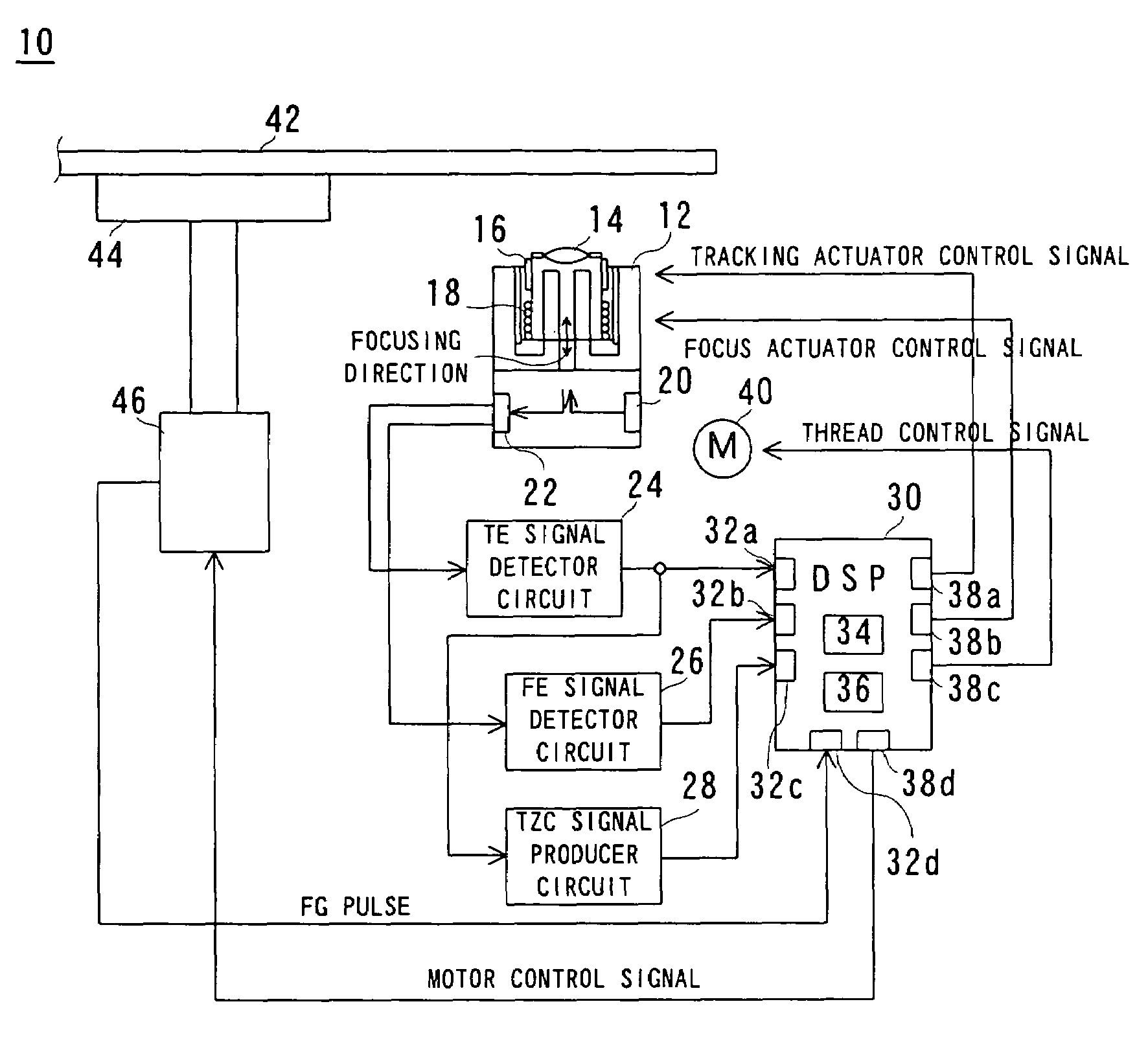
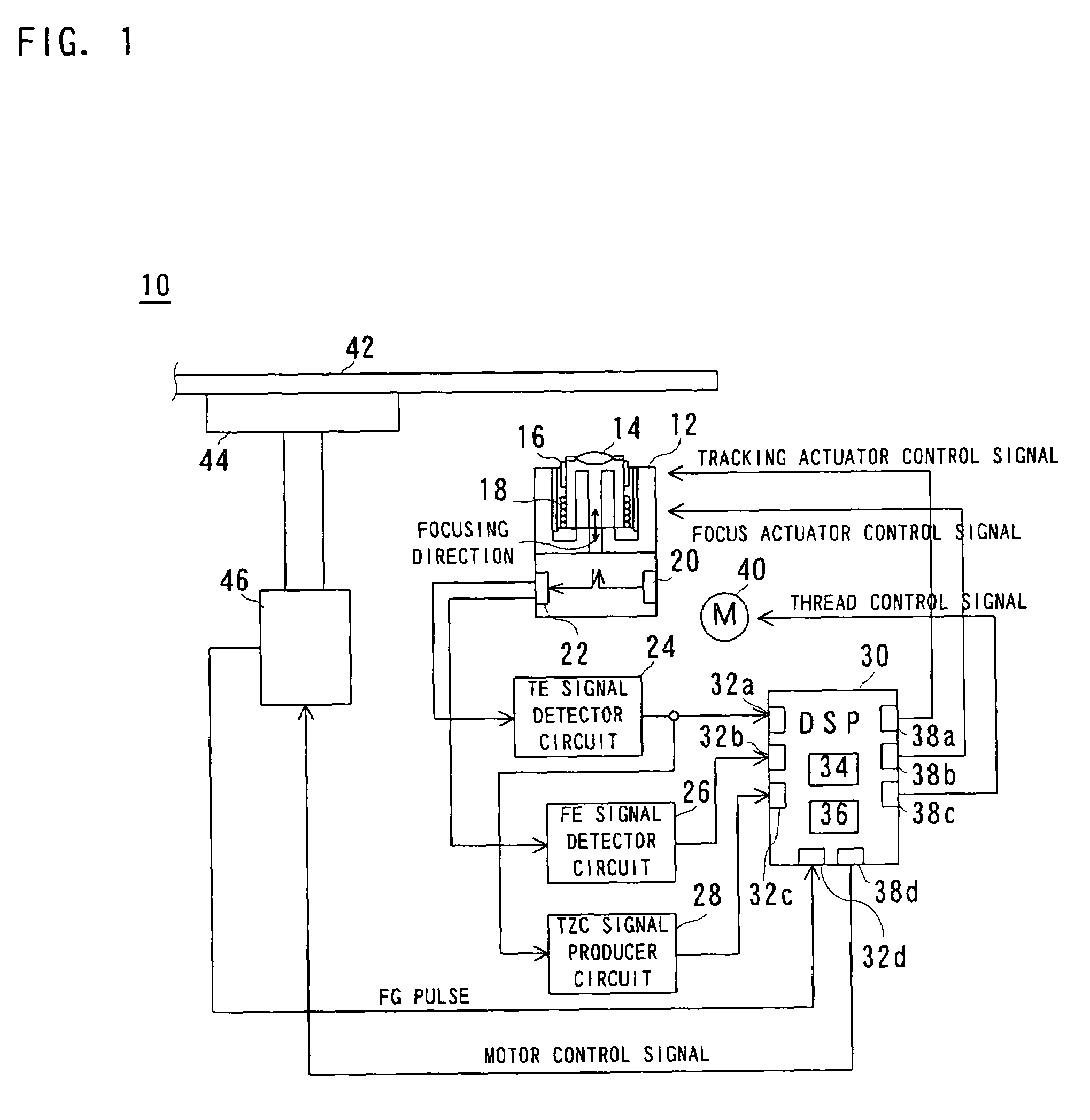
[0026]Referring to FIG. 1, a disk apparatus 10 of this embodiment includes an optical pickup 12. The optical pickup 12 includes an optical lens (objective lens) 14. The objective lens 14 is supported by a tracking actuator 16 and a focus actuator 18. Consequently, the laser light emitted from a laser diode 20 is converged by the objective lens 14 and illuminated to a reproducing surface of a magnet-optical disk (ASMO disk) 42. This enables to read a desired signal out of the ASMO disk (hereafter, merely referred to as “MO disk”) 42. Incidentally, the MO disk 42 is a disk capable of lands / groove-recording. Also, the optical pickup 12 is coupled to a thread motor 40, for example, through a lack-and-pinion scheme, and hence can be moved in a radial direction of the MO disk 42.

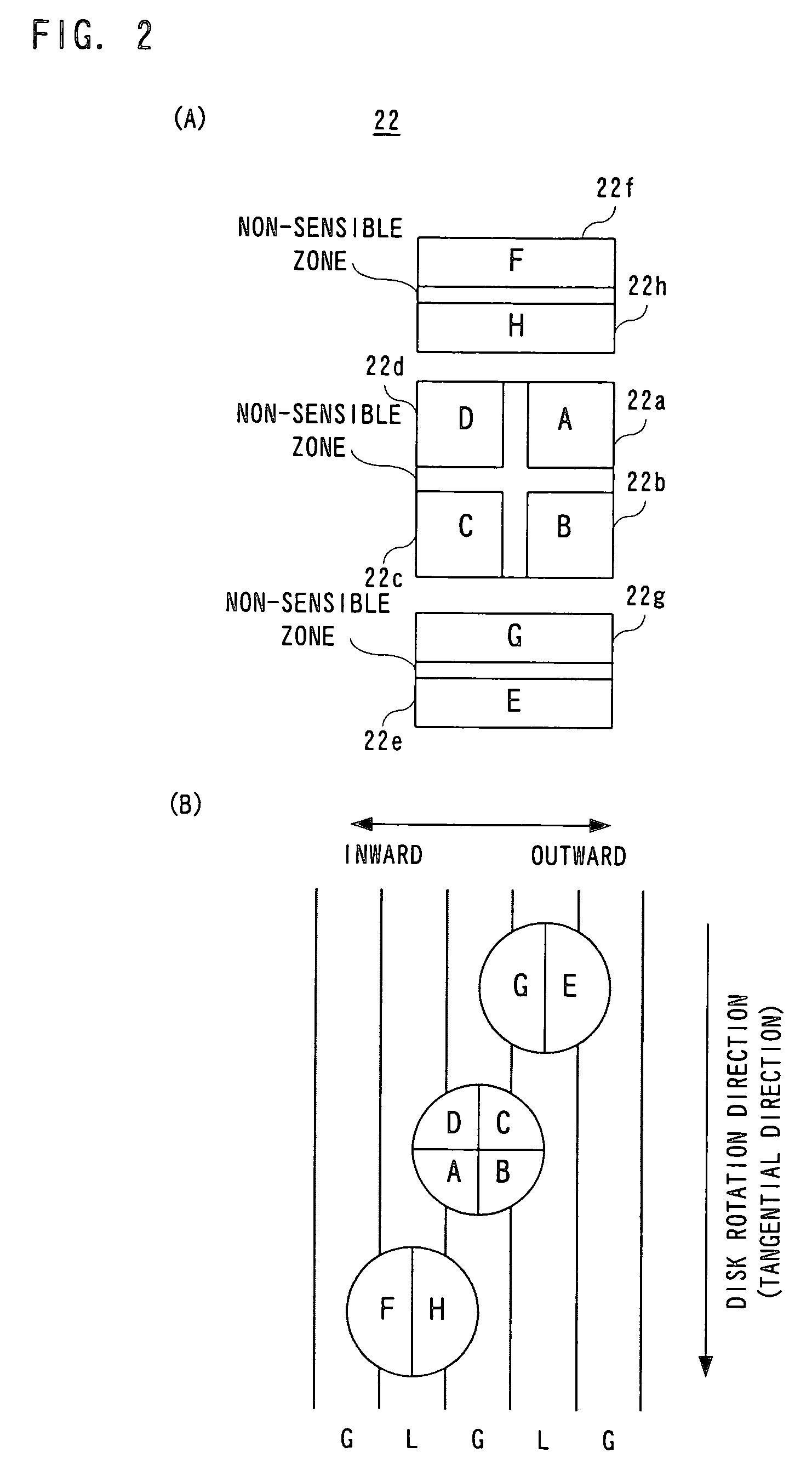
[0027]The laser light reflected upon a disk surface passes through the same objective lens 14 and illuminated to a photodetector 22. The photodetector 22 has an output to be inputted to a TE signal detecting circu...


PUM


Abstract

A disk apparatus includes a DSP core. If given an instruction to skip music during reproducing with an MO disk, the DSP core sets to a counter a count value corresponding to the number of tracks to jump over. Then, tracking servo is turned off and an optical pickup is moved in a radial direction of the MO disk. The DSP core detects rising and trailing edges in a TZC signal and counts down the counter. When the count value becomes 1, a level of the TZC signal is determined to judge whether there is variation in offset value or not. If there is variation in offset value, edges are considered counted incorrect. Accordingly, the count value is incremented. Thus, jump can be made to a desired land or groove, i.e. access can be made positively to a target position.

Description

BACKGROUND OF THE INVENTION[0001]1. Field of the Invention[0002]This invention relates generally to disk apparatuses and, more particularly, to a disk apparatus for setting to a counter a count value corresponding to the number of tracks to jump over, subtracting the count value each time a rising or trailing edge is detected in the zero-cross signal, and applying brake to finish jump when the count value reaches 0.[0003]2. Description of the Prior Art[0004]In the conventional disk apparatus of this kind, when seek is instructed, a count value is set to a counter correspondingly to the number of tracks to jump over. When the optical pickup is moved in a radial direction of the disk, counting is made on rising and trailing edges of a zero-cross (TZC) signal switching between high and low levels at zero-cross points of a tracking error (TE) signal. If the remaining count value reaches 1, a brake pulse is outputted to decelerate the optical pickup and turn on tracking servo. In this ma...

Claims


Application Information

Patent Timeline
IPC IPC(8): G11B21/08G11B7/007G11B7/085G11B11/105G11B19/20
CPCG11B7/00718G11B7/08541G11B7/08517G11B11/10563G11B19/20
Inventor OKAJIMA, TADASHI
Owner SANYO ELECTRIC CO LTD
Why Eureka
Try Eureka