
Condensate overflow prevention apparatus

a technology of condensate overflow and apparatus, which is applied in the direction of domestic cooling apparatus, heating types, instruments, etc., can solve the problems of water damage, inability to prevent the air cooling system from producing more condensate,

Inactive Publication Date: 2005-12-20
RECTORSEAL
View PDF17 Cites 37 Cited by
  • Summary
  • Abstract
  • Description
  • Claims
  • Application Information

AI Technical Summary

Benefits of technology

Effectively evacuates excess condensate before it overflows, reducing the risk of water damage and property loss by continuously removing condensate even after the air cooling system has stopped operating.

Problems solved by technology

However, shutting down the air cooling system does not prevent the air cooling system from producing further condensate due to residual cold coolant remaining in the heat exchange coils.
The condensate can continue to drip into the drain pan, and eventually, the rising condensate can overflow from the drain pan causing water damage even though the air cooling system has ceased operating and an alarm, if fitted, has been activated.

Method used


Image

  • Condensate overflow prevention apparatus
  • Condensate overflow prevention apparatus
  • Condensate overflow prevention apparatus

Examples


Embodiment Construction

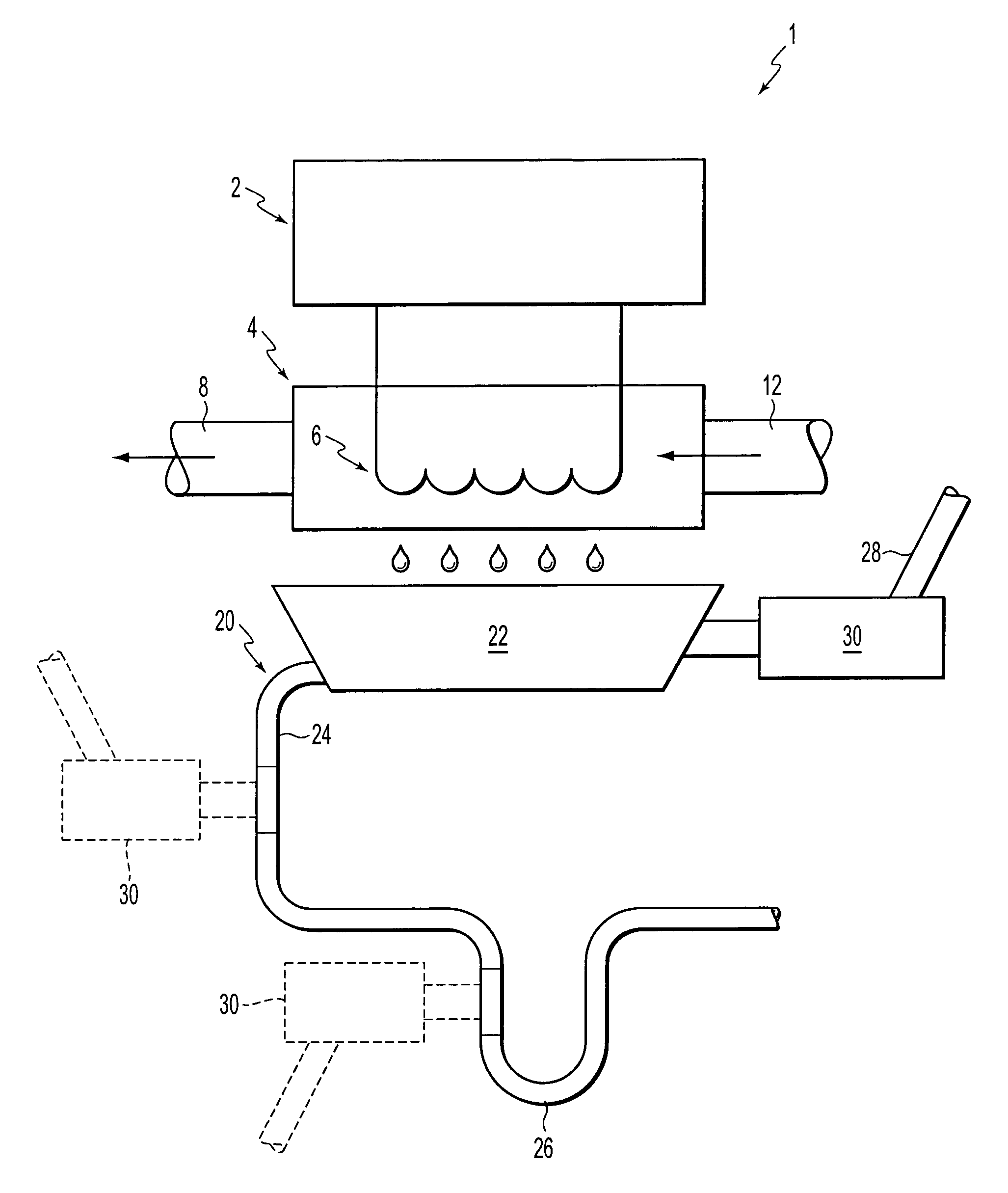
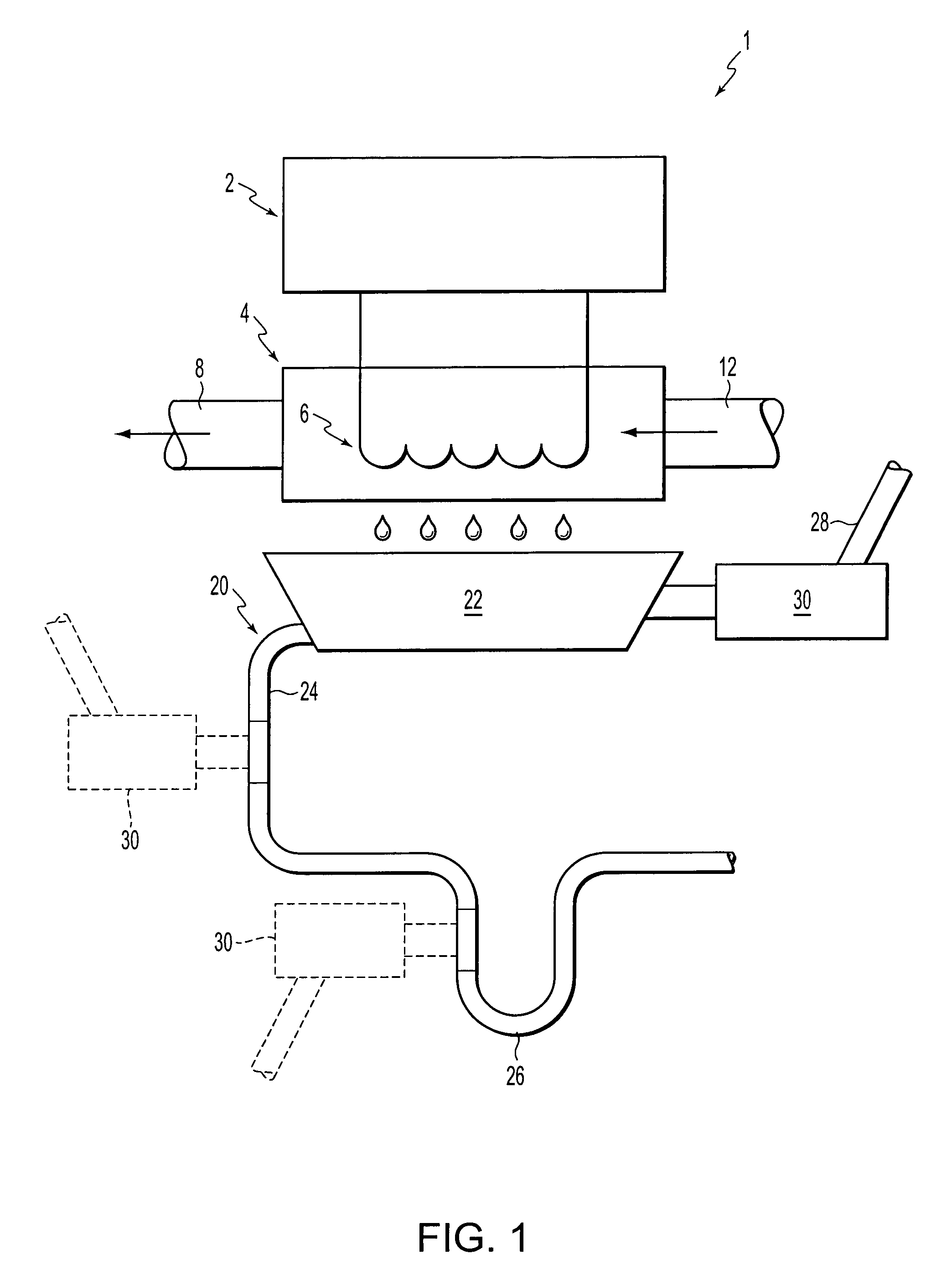
[0026]FIG. 1 illustrates an air cooling system 1 including a drainage system 20 that includes a condensate overflow prevention device 30 according to an exemplary embodiment of the present invention. The air cooling system 1 includes an air conditioner 2 coupled to an air handler 4. The air conditioner 2 circulates and cools a coolant passing through the air conditioner 2. The air handler 4 contains heat exchange coils 6 through which the cold coolant circulates. Warm air is conveyed to the air handler 4 through an inlet duct 12. The warm air is cooled as it makes contact with the exchange coils 6. The cool air is then transported away from air handler 4 through an outlet duct 8. When the warm air is cooled, moisture in the air condenses on the heat exchange coils 6 as liquid droplets or condensate.

[0027]The drainage system 20 includes a drain pan 22, a drain line 24 and at least one condensate overflow prevention device 30. The drainage system 20 also may include a condensate trap ...


PUM


Abstract

A condensate overflow prevention assembly prevents condensate overflow in an air cooling system using a fluid level sensor and a pump activated by the fluid level sensor to pump the condensate away from a drainage system when a blockage occurs in the drainage system.

Description

BACKGROUND OF THE INVENTION[0001]1. Field of Invention[0002]The present invention relates to a condensate overflow prevention apparatus for use with an air cooling system, and in particular to a condensate overflow prevention apparatus that uses a pump.[0003]2. Description of Related Art[0004]An air cooling system, such as an air conditioner or a heat pump, typically has heat exchange coils that produce condensate as the system cools the air in a building. The condensate can cause damage to structures within the building, such as dry walls, ceilings, wooden supports, etc. Thus, the condensate is collected in a drain pan usually placed below the heat exchange coils, and is transported away through a drain line connected to the drain pan. Over a period of time, a blockage can occur in the drain pan or the drain line due to debris, algae, mold, etc. The blockage causes the condensate to accumulate in the drain pan, and eventually, overflows to cause damage to the building.[0005]U.S. Pa...

Claims


Application Information

Patent Timeline
Patent Type & Authority Patents(United States)
IPC IPC(8): F24F13/22F25D21/14
CPCF24F13/222F25D21/14F24F2011/0054F24F2140/30
Inventor SPANGER, GERALD S.
Owner RECTORSEAL
Learn More