Compact air cooling system

Inactive Publication Date: 2009-10-22
MINEBEA CO LTD
View PDF13 Cites 34 Cited by
  • Summary
  • Abstract
  • Description
  • Claims
  • Application Information

AI Technical Summary

Benefits of technology

[0008]Many benefits are achieved by applying embodiments of the present invention. An embodiment enhances the heat removal process by utilizing the blower bladed-diffuser. Each of the diffuser blades or fins is a heat sink and surfaces of diffuser plate act as a heat spreader. Another embodiment with the blower impeller being embedded in the central portion of the diffuser fins makes the overall unit very compact

Problems solved by technology

But, the axial fan usually is deployed separately which takes more space; the one-dimensional inflow of cold air and outflow of hot air are sometime not efficient enough to remove heat out of the assembly.
In many new electronics applications, reduced product dime

Method used


Image

  • Compact air cooling system
  • Compact air cooling system
  • Compact air cooling system

Examples


Embodiment Construction

[0015]The present invention relates generally to fluid flow processing techniques, and in particular to an apparatus that integrally combines a motorized blower with radial impeller blades in association with diffuser fins over a conductive plate into a single compact unit and a method of generating radial air flow to effectively cool an object by both conduction and convention. But it should be applicable to much broader areas of fluid flow processing.

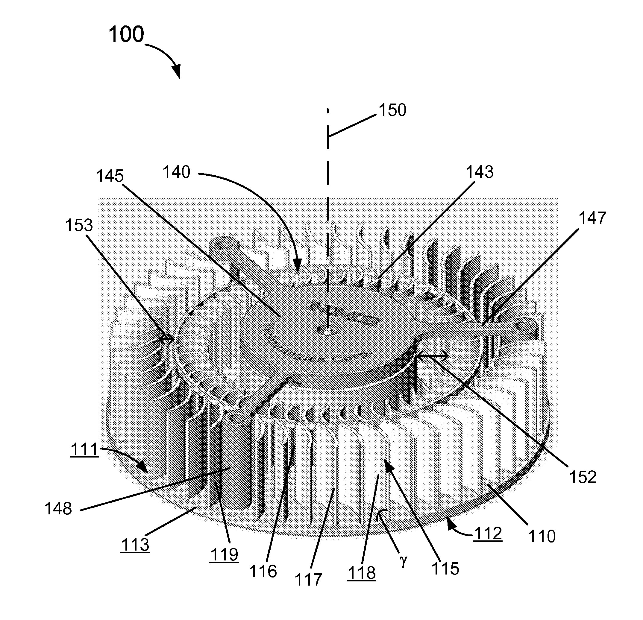
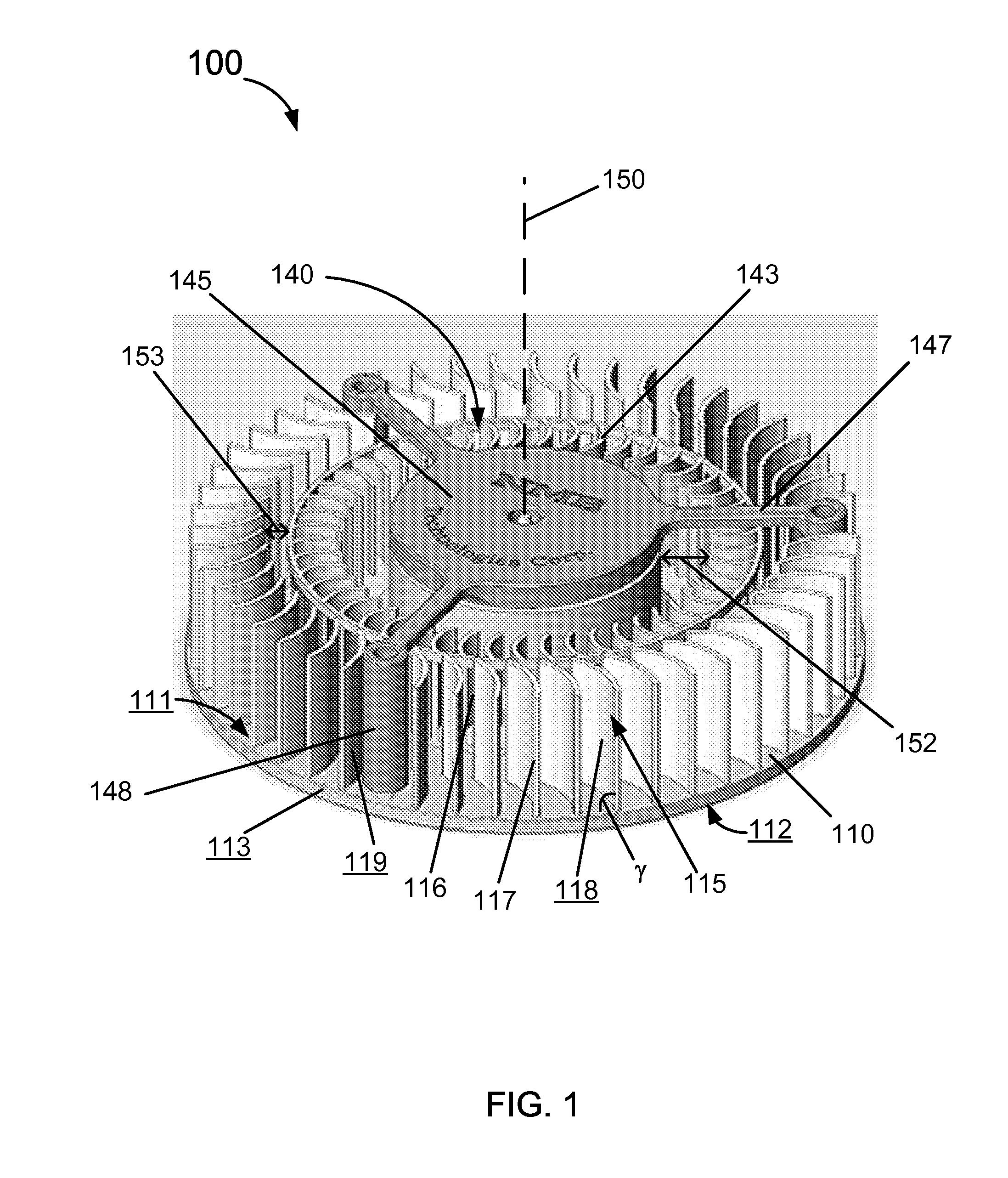
[0016]FIG. 1 is a schematic diagram of an assembled apparatus according to an embodiment of the present invention. This diagram is merely an example, which should not unduly limit the scope of the claims herein. One of ordinary skill in the art would recognize many variations, alternatives, and modifications. As shown, the apparatus 100 includes a base plate 110 which is made from heat-conducting materials and can have a variety of shapes. For example, the shape can be a polygon, a circle, an oval, or others. Preferably the base plate...


PUM


Abstract

An apparatus for air cooling an object. The apparatus includes a plate including a first surface and a second surface and a plurality of aerodynamic fins being fixedly disposed on the first surface in an arrangement along periphery of the plate. The arrangement of the plurality of aerodynamic fins defining a central volume of space. Additionally, the apparatus includes a blower including a plurality of impeller blades rotatably disposed within the central volume of space for rotary motion about an axis of rotation. In particular, the second surface is for thermally contacting with the object and the axis of rotation is substantially perpendicular to the first surface. Furthermore, the rotary motion of the blower creates an air inflow along the axis of rotation into the central volume of space and an air outflow through the plurality of aerodynamic fins in radial directions.

Description

BACKGROUND OF THE INVENTION[0001]The present invention relates generally to fluid flow processing techniques, and in particular to a method and an apparatus for effectively air cooling of an object via both conduction and convention.[0002]In conventional techniques diffusing heat sink is usually not an integral part of a blower. In certain conventional applications, for example, for cooling an assembly of electronics products, an axial fan is usually deployed for creating an one directional flow of air above a heated area to take the heat away. But no conducting plate is used. In certain improved applications, heat sink fins may be applied on top of the heated area so that heat firstly is conducted from the operating hot devices through a conductive plate to the heat sink fins and the air within the assembly is heated. Then the axial fan creates an air flow to remove the hot air out in substantially one direction. But, the axial fan usually is deployed separately which takes more sp...

Claims


Application Information

Patent Timeline
IPC IPC(8): F03D7/06
CPCF04D25/0613F04D29/582F04D29/444
Inventor JARRAH, YOUSEF
Owner MINEBEA CO LTD
Why Eureka
Try Eureka