High capacity air-cooling systems for electronic apparatus

a technology of air-cooling system and electronic equipment, which is applied in the direction of domestic cooling apparatus, electric apparatus casing/cabinet/drawer, instruments, etc., can solve the problems of ever accelerating the requirement to dissipate the thermal energy or heat produced by equipment, server equipment damage, and heat dissipation can become a significant concern

Inactive Publication Date: 2005-02-10
INTEL CORP
View PDF7 Cites 32 Cited by
  • Summary
  • Abstract
  • Description
  • Claims
  • Application Information

AI Technical Summary

Problems solved by technology

Because such equipment operates at higher and higher power levels, there is, as a direct consequence, an ever accelerating requirement to dissipate the thermal energy or heat produced by the equipment.
To compound the problem, when a server at this performance level is packaged in an industry-standard “1U” height server (i.e. only 1.75 inches (4.445 cm) in height), heat dissipation can become a significant concern.
If the heat is not adequately dissipated, the server equipment could be damaged, or the processors could be automatically throttled down to operate at a slower speed than their nominal rating.
In the past, relatively high performance electronic equipment generally required larger, more complex, and more powerful cooling solutions, as well as a corresponding increase in the size of the equipment cabinet or other type of equipment housing.
These fans, and their associated airflow ducting, can consume an enormous amount of real estate on the chassis.
They also contribute substantially to the cost, complexity, size, and height of the computer system, not to mention the additional noise that they produce due to the fact they typically run at high RPM, e.g. exceeding 10,000 RPM.
Floor space for server racks is expensive, and it is desirable to pack as much computer performance into as small a space as possible.
However, for the reasons set forth above, this can create significant heat dissipation problems.

Method used


Image

  • High capacity air-cooling systems for electronic apparatus
  • High capacity air-cooling systems for electronic apparatus
  • High capacity air-cooling systems for electronic apparatus

Examples


Embodiment Construction

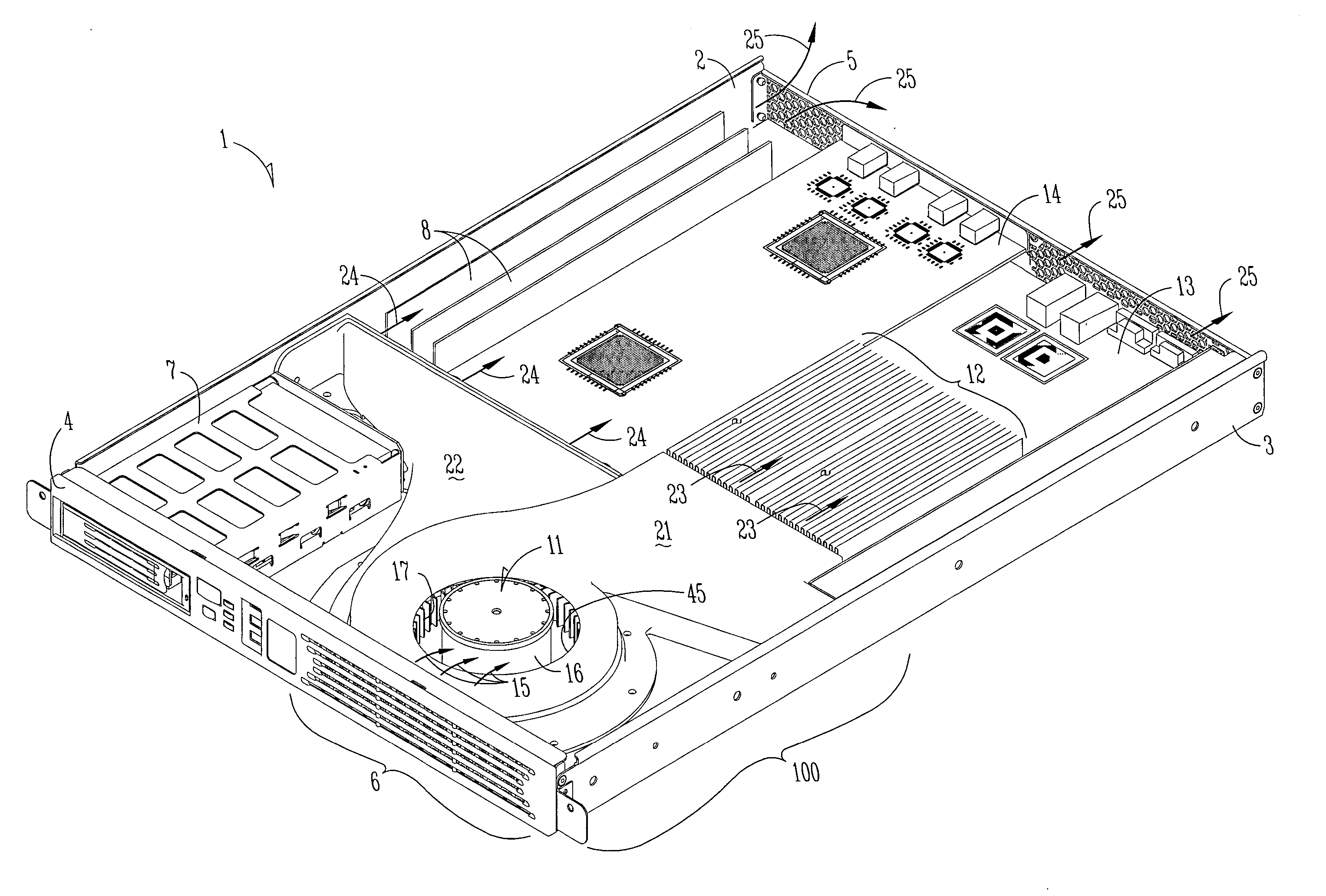
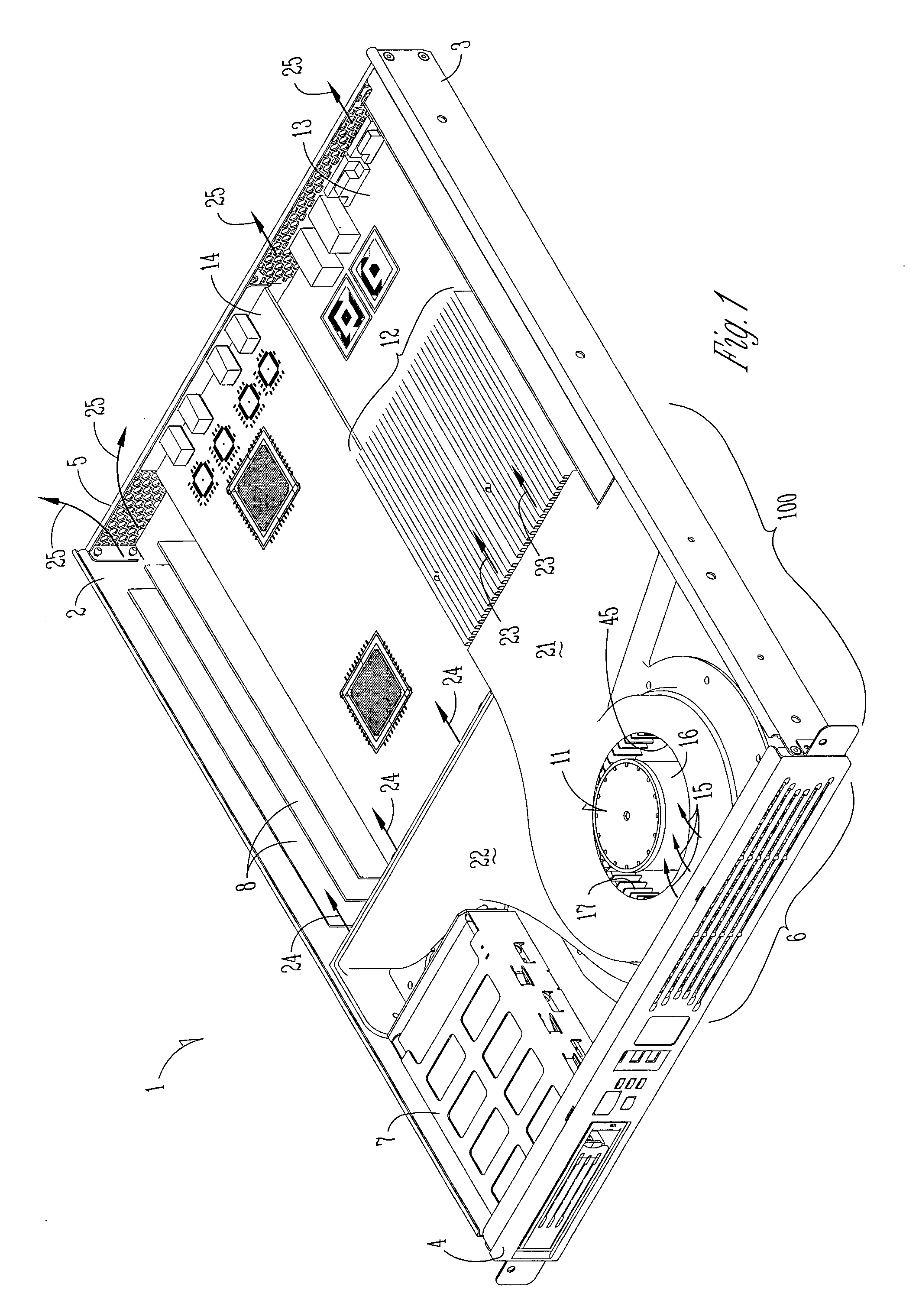
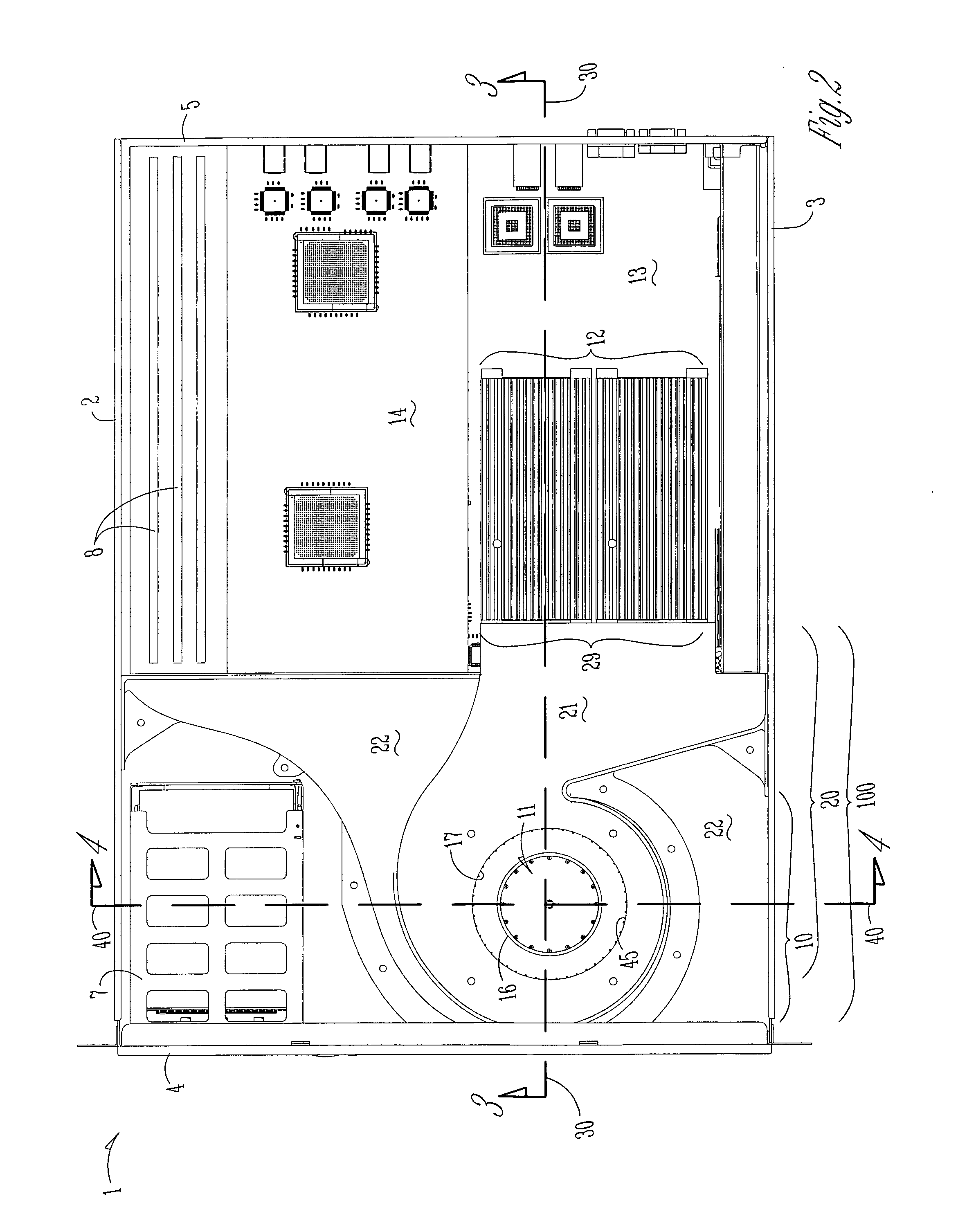
[0024] In the following detailed description of embodiments of the inventive subject matter, reference is made to the accompanying drawings which form a part hereof, and in which is shown by way of illustration specific preferred embodiments in which the inventive subject matter may be practiced. These embodiments are described in sufficient detail to enable those skilled in the art to practice the inventive subject matter, and it is to be understood that other embodiments may be utilized and that mechanical, compositional, structural, electrical, and procedural changes may be made without departing from the spirit and scope of the inventive subject matter. The following detailed description is, therefore, not to be taken in a limiting sense, and the scope of the inventive subject matter is defined only by the appended claims.

[0025] The subject matter provides a solution to the need to efficiently and quietly dissipate heat that is generated by high performance electronic equipment...


PUM


Abstract

An improved air-cooling system for high performance, high density electronic equipment comprises, in one embodiment, a single fan having a radial impeller, a baffle having an inlet portion to efficiently direct air into the fan intake, and a two-tiered outlet plenum to direct one airflow specifically at the highest heat-generating components and another airflow at all components. The air-cooling system is designed to provide maximum cooling for a low-height, high heat-generating electronics module such as a server. By using only a single fan that is matched to the low resistance airflow characteristics of the baffle, the air-cooling system offers significant advantages over multi-fan systems. Also described are a computer server and methods of making heat-dissipation equipment.

Description

DIVISIONAL APPLICATION [0001] The present application is a divisional of application U.S. Ser. No. 09 / 896,869, filed on Jun. 29, 2001, which is incorporated herein by reference.TECHNICAL FIELD [0002] The subject matter relates generally to heat dissipation in electronic apparatus. More particularly, the subject matter relates to an improved air-cooling system for high density electronic equipment. BACKGROUND INFORMATION [0003] Computer networks, such as the Internet, utilize high performance computer systems called “servers”. Servers typically have high performance processors and contain hardware and software capable of handling large amounts of data. Servers provide a large number of computer users with access to large stores of information. For example, servers are used to host web sites that can be accessed by many computers via the Internet. [0004] One or more server components are often housed within a server housing or “server rack”. Server racks are typically box-like structu...

Claims


Application Information

Patent Timeline
Patent Type & Authority Applications(United States)
IPC IPC(8): H05K7/20
CPCH05K7/20727
Inventor FANEUF, BARRETT M.BERRY, WILLIAM E.HOLALKERE, VEN R.
Owner INTEL CORP
Why Eureka
Try Eureka