Eureka AIR delivers breakthrough ideas for toughest innovation challenges, trusted by R&D personnel around the world.

Mechanically actuated, electronically controlled fuel injection system

Inactive Publication Date: 2005-12-20
CATERPILLAR INC
View PDF13 Cites 19 Cited by
  • Summary
  • Abstract
  • Description
  • Claims
  • Application Information

AI Technical Summary

Benefits of technology

[0006]In one aspect, a fuel injection system includes a fuel pressurizer that includes a cam driven plunger, a fuel pressurization chamber and an electronically controlled spill valve that includes a first electrical actuator. A needle valve includes a member with a closing hydraulic surface exposed to fluid pressure in a needle control chamber. An electronically controlled needle control valve includes a second electrical actuator operably coupled to a control valve member that is biased toward a first position, but moveable to a second position when the second electrical actuator is energized. The needle control chamber is fluidly blocked from the fuel pressurization chamber when the control valve member is in its first position, but fluidly connected to the fuel pressurization chamber when the control

Problems solved by technology

In certain rare circumstances, these fuel injection systems have the potential for becoming overpressurized in a way that could possibly lead to injector as well as engine damage.
In such circumstances, it is possible for the fuel injector to become pressurized in a typical manner by electronically closing the spill valve; however, no injection is able to occur since a failure in the electronics for the needle control valve prevent the nozzle from opening, since the electronic failure prevents energization of a second electrical actuator to relieve pressure on the closing hydraulic surface of the needle valve member.
In these rare circumstances, tip breakage can occur or the linkage between the rotating cam and the injector tappet can become overstressed and break.
In any event, this potential failure mode can possibly result in catastrophic engine failure if even one fuel injector becomes overpressurized and its tip breaks off into an engine cylinder.

Method used


Image

  • Mechanically actuated, electronically controlled fuel injection system
  • Mechanically actuated, electronically controlled fuel injection system
  • Mechanically actuated, electronically controlled fuel injection system

Examples


Embodiment Construction

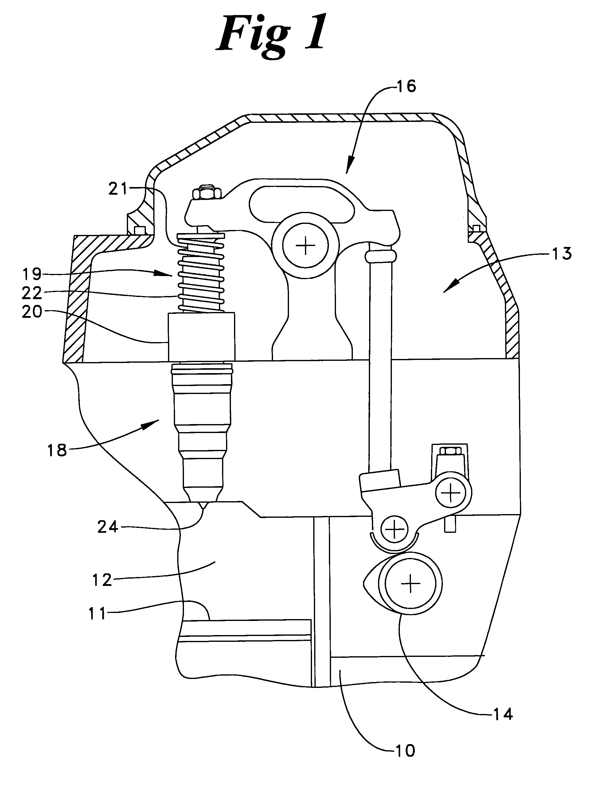
[0011]Referring now to FIG. 1, an engine 10 includes a reciprocating piston 11 in a cylinder 12. A fuel injection system 13 is driven by a cam 14 via a rocker arm assembly 16 to actuate a fuel injector 18. Fuel injector 18 includes an injector body 20 within which a fuel pressurizer 19 is partially housed. Fuel pressurizer 19 includes a tappet 21 that is linked to rocker arm assembly 16 in a manner well known in the art. Contact between the tappet and rocker arm assembly is maintained via a return spring 22 in a conventional manner. Those skilled in the art will recognize that the lobe of cam 14 causes tappet 21 to be driven downward to pressurize fuel in fuel pressurizer 19, which is then injected into cylinder 12 via nozzle outlet set 24.

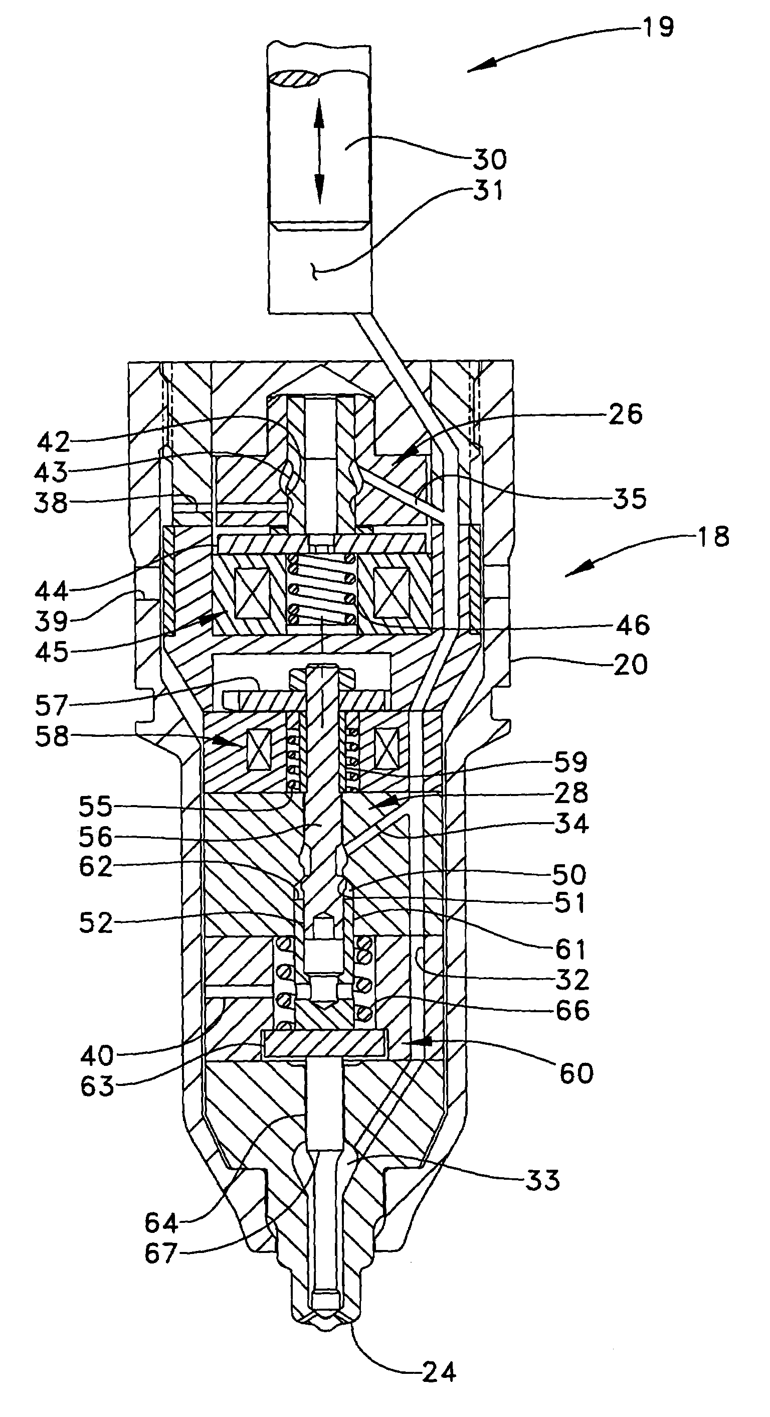
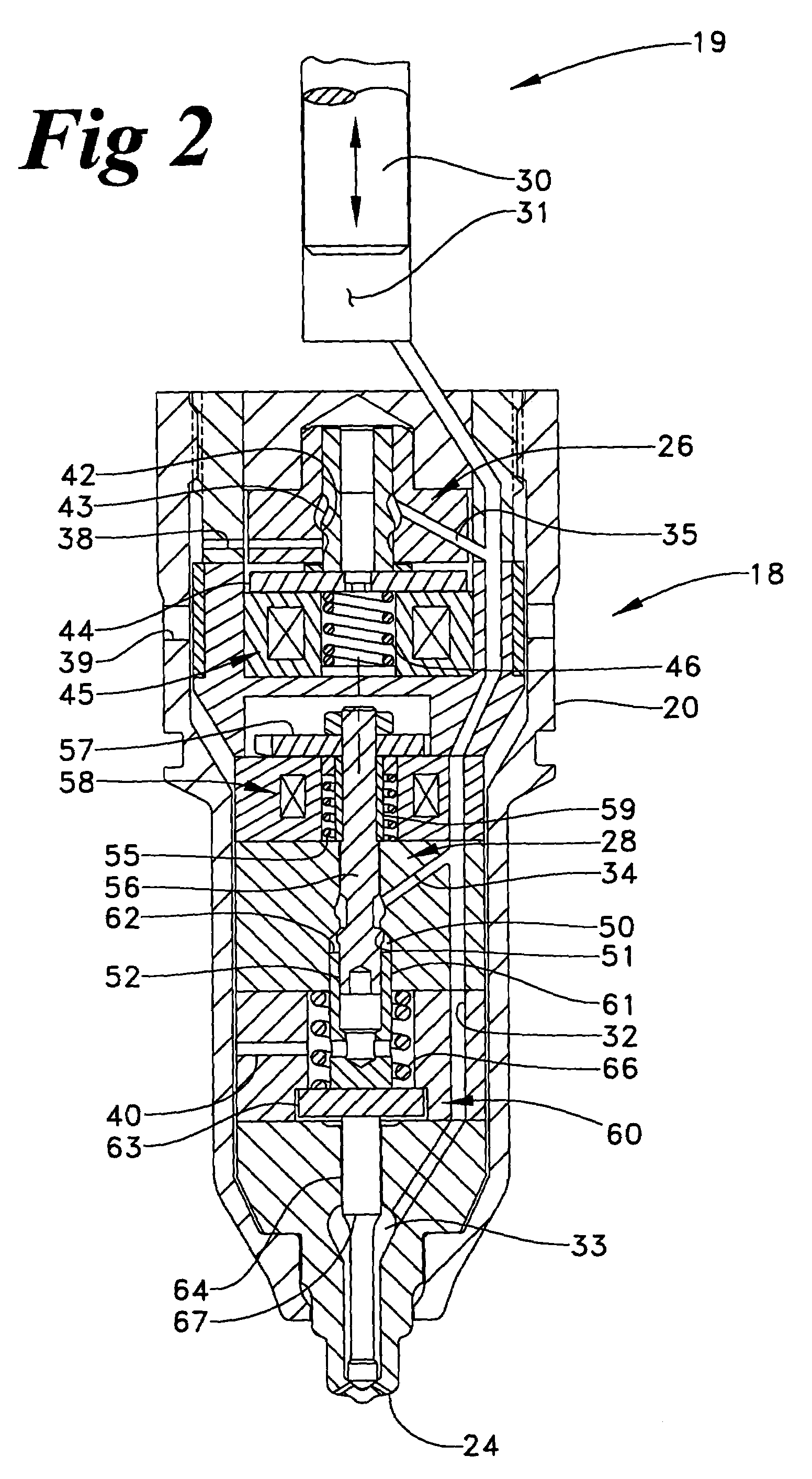
[0012]Referring now in addition to FIG. 2, fuel pressurizer 19 includes a plunger 30 that is operably coupled to tappet 21. Plunger 30 and fuel injector body 20 together define a fuel pressurization chamber 31 that is fluidly connected to nozzle c...


PUM


Abstract

A fuel injection system includes a fuel pressurizer that may be cam actuated. The fuel injection system also includes an electronically controlled spill valve and an electronically controlled needle control valve. The energization of the electronically controlled spill valve closes a fuel pressurization chamber to a drain passage to allow fuel pressure in the fuel injector to build to injection levels. The electronically controlled needle control valve controls whether high or low fuel pressure is applied to a closing hydraulic surface associated with a direct control needle valve. The fuel injection system includes a hydraulic circuitry that allows for fuel injection to occur by either maintaining the electronically controlled needle control valve in a de-energized state, or by de-energizing the same, after fuel pressure within the fuel injector has built to injection levels. With a de-energize to inject hydraulic circuitry associated with the direct control needle valve, the fuel injection system can prevent overpressurization in the event of electrical failure in the needle control electronic circuitry. This also provides a fuel engine with a limp home capability in the case of such an electronic problem. In addition, the fuel injection system can have reduced overall power requirements that can lead to downsizing and other cost saving advantages.

Description

TECHNICAL FIELD[0001]The present disclosure relates generally to fuel injection systems that are mechanically actuated and electronically controlled, and more particularly to such a fuel injection system in which an electronically controlled needle control valve is de-energized to inject fuel.BACKGROUND[0002]Mechanically actuated fuel injectors typically have a fuel pressurizer that includes a plunger that is driven to reciprocate by a cam rotated by an engine. The fuel pressurizer can be in a separate body from the fuel injector, such as in a unit pump. However, more typically, the fuel pressurizer and injection nozzle are carried in a common injector body. Some electronic control was initially introduced to these fuel injection systems by including an electronically controlled spill valve. In other words, as the cam rotates, fuel pressure does not develop in the fuel injector until the spill valve is closed. When the spill valve is open, fuel displaced by downward movement of the ...

Claims


Application Information

Patent Timeline
IPC IPC(8): F02M37/04F02M47/02F02M57/02F02M59/36
CPCF02M47/027F02M57/023F02M59/366
Inventor COLDREN, DANA R.LEWIS, STEPHEN R.HUFFMAN, MICHAEL R.
Owner CATERPILLAR INC
Why Eureka
Eureka Blog
Learn More